- 您現(xiàn)在的位置:買賣IC網(wǎng) > PDF目錄383357 > MAX3111ECNI (MAXIM INTEGRATED PRODUCTS INC) 5V High-Speed RS-232 Transceivers with 0.1uF Capacitors PDF資料下載
參數(shù)資料
| 型號(hào): | MAX3111ECNI |
| 廠商: | MAXIM INTEGRATED PRODUCTS INC |
| 元件分類: | 微控制器/微處理器 |
| 英文描述: | 5V High-Speed RS-232 Transceivers with 0.1uF Capacitors |
| 中文描述: | 1 CHANNEL(S), SERIAL COMM CONTROLLER, PDIP28 |
| 封裝: | 0.300 INCH, PLASTIC, DIP-28 |
| 文件頁(yè)數(shù): | 2/32頁(yè) |
| 文件大小: | 413K |
| 代理商: | MAX3111ECNI |
第1頁(yè)當(dāng)前第2頁(yè)第3頁(yè)第4頁(yè)第5頁(yè)第6頁(yè)第7頁(yè)第8頁(yè)第9頁(yè)第10頁(yè)第11頁(yè)第12頁(yè)第13頁(yè)第14頁(yè)第15頁(yè)第16頁(yè)第17頁(yè)第18頁(yè)第19頁(yè)第20頁(yè)第21頁(yè)第22頁(yè)第23頁(yè)第24頁(yè)第25頁(yè)第26頁(yè)第27頁(yè)第28頁(yè)第29頁(yè)第30頁(yè)第31頁(yè)第32頁(yè)

M
SPI/MICROWIRE-Compatible UART and ±15kV ESD-
Protected RS-232 Transceivers with Internal Capacitors
2
_______________________________________________________________________________________
ABSOLUTE MAXIMUM RATINGS
V
CC
to GND (MAX3110E) ........................................-0.3V to +6V
V
CC
to GND (MAX3111E).........................................-0.3V to +4V
V+ to GND (Note 1)..................................................-0.3V to +7V
V- to GND (Note 1)...................................................+0.3V to -7V
V+ to V- (Note 1)..................................................................+13V
Input Voltages to GND
CS
, X1,
CTS
, RX, DIN, SCLK.................. -0.3V to (V
CC
+ 0.3V)
T_IN,
SHDN
...........................................................-0.3V to +6V
R_IN..................................................................................±25V
Output Voltage to GND
DOUT,
RTS
, TX, X2 .................................-0.3V to (V
CC
+ 0.3V)
IRQ
.......................................................................-0.3V to +6V
T_OUT ...........................................................................±13.2V
R_OUT.....................................................-0.3V to (V
CC
+ 0.3V)
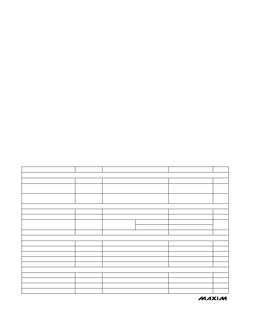
ELECTRICAL CHARACTERISTICS—MAX3110E
(V
CC
= +4.5V to +5.5V, T
A
= T
MIN
to T
MAX
, unless otherwise noted. Typical values are measured for baud rate set to 9600baud at
V
CC
= +5V, T
A
= +25°C.) (Note 2)
PARAMETER
SYMBOL
CONDITIONS
DC CHARACTERISTICS
(V
CC
= +5V, T
A
= +25°C)
Stresses beyond those listed under “Absolute Maximum Ratings” may cause permanent damage to the device. These are stress ratings only, and function-
al operation of the device at these or any other conditions beyond those indicated in the operational sections of the specifications is not implied. Exposure
to absolute maximum rating conditions for extended periods may affect device reliability.
TX,
RTS
Output Current ....................................................100mA
Short-Circuit Duration
X2, DOUT,
IRQ
(to V
CC
or GND).............................Continuous
T_OUT (to GND) .....................................................Continuous
Continuous Power Dissipation (T
A
= +70°C)
28-pin Wide SO (derate 12.5mW/°C above +70°C) ...........1W
28-pin Plastic DIP (derate 14.3mW/°C above +70°C) ....1.14W
Operating Temperature Ranges
MAX311_EC_ _ .................................................. 0°C to +70°C
MAX311_EE_ _ ................................................-40°C to +85°C
Storage Temperature Range ............................-65°C to +150°C
Lead Temperature (soldering, 10sec).............................+300°C
Note 1:
V+ and V- can have maximum magnitudes of 7V, but their absolute difference should not exceed 13V.
SHDNi bit = 1
SHDNi bit = 0
2
Input Current
I
IN1
25
μA
V
X1
= 0 or 5.5V
MIN
TYP
MAX
UNITS
Input Low Voltage
V
IL1
0.2V
CC
V
Input High Voltage
V
IH1
0.7V
CC
V
V
Supply Current with Hardware
and Software Shutdown
UART OSCILLATOR INPUT (X1)
I
CCSHDN(H+ S)
3
20
μA
Input Capacitance
UART LOGIC INPUTS (DIN, SCLK,
CS, CTS
, RX
)
C
IN1
5
pF
Input High Voltage
Input Low Voltage
Input Hysteresis
Input Leakage Current
Input Capacitance
RS-232 LOGIC INPUTS (T_IN,
SHDN)
V
IH2
V
IL2
V
HYST2
I
LKG1
C
IN2
0.7V
CC
V
V
0.3V
CC
Supply Current
Supply Current with Hardware
Shutdown
I
CC
0.6
2
mA
I
CCSHDN(H)
0.48
1
mA
250
mV
μA
pF
±1
5
Input High Voltage
Input Low Voltage
Transmitter Input Hysteresis
Input Leakage Current
V
IH3
V
IL3
V
HYST3
I
IN3
2.4
0.8
V
500
±0.01
mV
μA
±1
SHDN
= GND, SHDNi bit = 1 (Note 4)
V
CC
= 5V
SHDN
= V
CC
, no load
SHDN
= GND (Note 3)
相關(guān)PDF資料 |
PDF描述 |
|---|---|
| MAX3111ECWI | 5V High-Speed RS-232 Transceivers with 0.1uF Capacitors |
| MAX3110EEWI | 5V High-Speed RS-232 Transceivers with 0.1uF Capacitors |
| MAX3111EEWI | 5V High-Speed RS-232 Transceivers with 0.1uF Capacitors |
| MAX3110ECNI | 5V High-Speed RS-232 Transceivers with 0.1uF Capacitors |
| MAX3120CUA | Low-Profile, 3V, 120レA, IrDA Infrared Transceiver |
相關(guān)代理商/技術(shù)參數(shù) |
參數(shù)描述 |
|---|---|
| MAX3111ECNI+G36 | 功能描述:UART 接口集成電路 5V SPI/uWire Compatible RoHS:否 制造商:Texas Instruments 通道數(shù)量:2 數(shù)據(jù)速率:3 Mbps 電源電壓-最大:3.6 V 電源電壓-最小:2.7 V 電源電流:20 mA 最大工作溫度:+ 85 C 最小工作溫度:- 40 C 封裝 / 箱體:LQFP-48 封裝:Reel |
| MAX3111ECW1+G36 | 制造商:IC'S/TRANSISTORS/DIO 功能描述: 制造商:IC'S/TRANSISTORS/DIODES 功能描述: |
| MAX3111ECWI | 功能描述:UART 接口集成電路 RoHS:否 制造商:Texas Instruments 通道數(shù)量:2 數(shù)據(jù)速率:3 Mbps 電源電壓-最大:3.6 V 電源電壓-最小:2.7 V 電源電流:20 mA 最大工作溫度:+ 85 C 最小工作溫度:- 40 C 封裝 / 箱體:LQFP-48 封裝:Reel |
| MAX3111ECWI+ | 制造商:Maxim Integrated Products 功能描述:LINE TRNSCVR 2TR 2TX 2RX 28SOIC W - Rail/Tube |
| MAX3111ECWI+G36 | 功能描述:UART 接口集成電路 5V SPI/uWire Compatible RoHS:否 制造商:Texas Instruments 通道數(shù)量:2 數(shù)據(jù)速率:3 Mbps 電源電壓-最大:3.6 V 電源電壓-最小:2.7 V 電源電流:20 mA 最大工作溫度:+ 85 C 最小工作溫度:- 40 C 封裝 / 箱體:LQFP-48 封裝:Reel |
發(fā)布緊急采購(gòu),3分鐘左右您將得到回復(fù)。