- 您現(xiàn)在的位置:買賣IC網(wǎng) > PDF目錄384656 > MAX2105CWI (MAXIM INTEGRATED PRODUCTS INC) Direct-Conversion Tuner ICs for Digital DBS Applications PDF資料下載
參數(shù)資料
| 型號: | MAX2105CWI |
| 廠商: | MAXIM INTEGRATED PRODUCTS INC |
| 元件分類: | 通信及網(wǎng)絡(luò) |
| 英文描述: | Direct-Conversion Tuner ICs for Digital DBS Applications |
| 中文描述: | SPECIALTY TELECOM CIRCUIT, PDSO28 |
| 封裝: | SO-28 |
| 文件頁數(shù): | 2/16頁 |
| 文件大小: | 151K |
| 代理商: | MAX2105CWI |
AGC Input Bias Current
AGC Input Bias Current
M
Direc t-Conversion Tuner ICs for
Digital DBS Applic ations
2
_______________________________________________________________________________________
ABSOLUTE MAXIMUM RATINGS
V
CC
to GND..............................................................-0.5V to +7V
RFIN to
RFIN
..........................................................................±2V
LO to
LO
................................................................................±2V
AGC, MOD, RFIN,
RFIN
, LO,
LO
to GND.....-0.5V to (V
CC
+ 0.5V)
AGC Current.....................................................................±30mA
IDC to
IDC
, QDC to
QDC
.......................................................±2V
IOUT or QOUT to GND Short-Circuit Duration...................10sec
PSOUT to GND Short-Circuit Duration.................................None
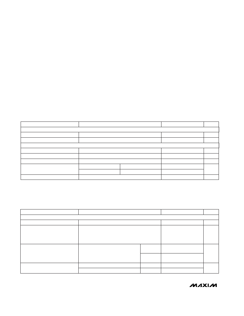
DC ELECTRICAL CHARACTERISTICS
(V
CC
= +4.75V to +5.25V; GND = 0V; PSGND = GND; AGC = 1.3V; MOD = 0.8V; P
RFIN
= OFF, f
LO
= 1450.125MHz; P
LO
= -15dBm;
IOUT, QOUT = open; T
A
= 0°C to +70°C; unless otherwise noted.)
CONDITIONS
PARAMETER
SUPPLY
AC ELECTRICAL CHARACTERISTICS
(MAX2102 EV kit circuit (Figure 1); V
CC
= +5V; PSGND = open; MOD = GND; f
RFIN
= 2150MHz; P
RFIN
= -19dBm; f
LO
=
2150.125MHz; P
LO
= -15dBm driven single-ended into LO; AGC set via servo loop for V
IOUT
= V
QOUT
= 0.5Vp-p; IOUT, QOUT drive
AC-coupled 100
loads; 2k
from PSOUT to GND; T
A
= +25°C; unless otherwise noted.)
Stresses beyond those listed under “Absolute Maximum Ratings” may cause permanent damage to the device. These are stress ratings only, and functional
operation of the device at these or any other conditions beyond those indicated in the operational sections of the specifications is not implied. Exposure to
absolute maximum rating conditions for extended periods may affect device reliability.
IDC,
IDC
, QDC,
QDC
to GND ....................-0.5V to (V
CC
+ 0.5V)
Continuous Power Dissipation (T
A
= +70°C)
SO (derate 12.5mW/°C above +70°C)..........................1.025W
Operating Temperature Range...............................0°C to +70°C
J unction Temperature......................................................+150°C
Storage Temperature Range.............................-65°C to +150°C
Lead Temperature (soldering, 10sec) .............................+300°C
MAX2102
MAX2105
0V
≤
V
MOD
≤
V
CC
mA
150
195
Quiescent Supply Current
CONTROL INPUTS, PRESCALER
V
4.75
5.25
Operating Supply Voltage Range
V
2.2
2.6
IOUT, QOUT Common-Mode Voltage
-250
-180
180
180
V
V
0.8
MOD Input Low Level
MOD Input High Level
MOD Input Bias Current
2.0
-80
μA
10
UNITS
MIN
TYP
MAX
Refers to single-carrier power generating
V
IOUT
= V
QOUT
= 0.5Vp-p,
950MHz < f
RFIN
< 2150MHz,
950MHz < f
LO
< 2150MHz (Note 2)
(Note 1)
Refers to single-carrier power generating
V
IOUT
= V
QOUT
= 0.5Vp-p,
950MHz < f
RFIN
< 2150MHz,
950MHz < f
LO
< 2150MHz (Note 2)
0.5V
≤
V
AGC
≤
4V
1V
≤
V
AGC
≤
4V
CONDITIONS
dBm
RFIN Maximum Single-Carrier
Input Power
MHz
950
2150
RFIN Carrier Frequency Range
dBm
-69
RFIN Minimum Single-Carrier
Input Power
50
41
UNITS
MIN
TYP
MAX
PARAMETER
-19
MAX2102
MAX2105
-60
dB
AGC Range
MAX2102
MAX2105
RF FRONT END
μA
0.5V
≤
V
AGC
≤
4V
1V
≤
V
AGC
≤
4V
相關(guān)PDF資料 |
PDF描述 |
|---|---|
| MAX2104 | 16-Bit Buffers/Drivers With 3-State Outputs 48-TSSOP -40 to 85 |
| MAX2104CCM | PLASTIC ENCAPSULATED DEVICES |
| MAX2106 | 16-Bit Buffers/Drivers With 3-State Outputs 48-TVSOP -40 to 85 |
| MAX2106UCM | DBS Direct Downconverter |
| MAX2108CEG | Direct-Conversion Tuner IC |
相關(guān)代理商/技術(shù)參數(shù) |
參數(shù)描述 |
|---|---|
| MAX2105CWI+ | 制造商:Rochester Electronics LLC 功能描述: 制造商:Maxim Integrated Products 功能描述: |
| MAX2106 | 制造商:MAXIM 制造商全稱:Maxim Integrated Products 功能描述:DBS Direct Downconverter |
| MAX2106_05 | 制造商:MAXIM 制造商全稱:Maxim Integrated Products 功能描述:DBS Direct Downconverter |
| MAX2106CCM | 制造商:MAXIM 制造商全稱:Maxim Integrated Products 功能描述:Analog IC |
| MAX2106ECM | 制造商:Rochester Electronics LLC 功能描述: 制造商:Maxim Integrated Products 功能描述: |
發(fā)布緊急采購,3分鐘左右您將得到回復(fù)。