- 您現(xiàn)在的位置:買賣IC網(wǎng) > PDF目錄383344 > MAX2016EVKIT (Maxim Integrated Products, Inc.) Evaluation Kit PDF資料下載
參數(shù)資料
| 型號: | MAX2016EVKIT |
| 廠商: | Maxim Integrated Products, Inc. |
| 英文描述: | Evaluation Kit |
| 中文描述: | MAX2016評估板 |
| 文件頁數(shù): | 4/9頁 |
| 文件大小: | 238K |
| 代理商: | MAX2016EVKIT |

E
Detector Mode
The MAX2016 EV kit is assembled with a 0
resistor for
R3. This sets the slope of the difference output signal,
VOUTD, to approximately -25mV/dB (RF = 100MHz). To
increase the slope of the difference output signal,
increase the value of R3. For example, if a 20k
resis-
tor is used for R3, the slope for the difference signal
increases to -50mV/dB.
The bandwidth and response time of the difference out-
put amplifier can be controlled with an external capaci-
tor, C15. With no external capacitor, the bandwidth is
greater than 20MHz. Refer to the
Applications
Information
section in the MAX2016 data sheet for the
equation to calculate the required capacitance.
Gain-Controller Mode
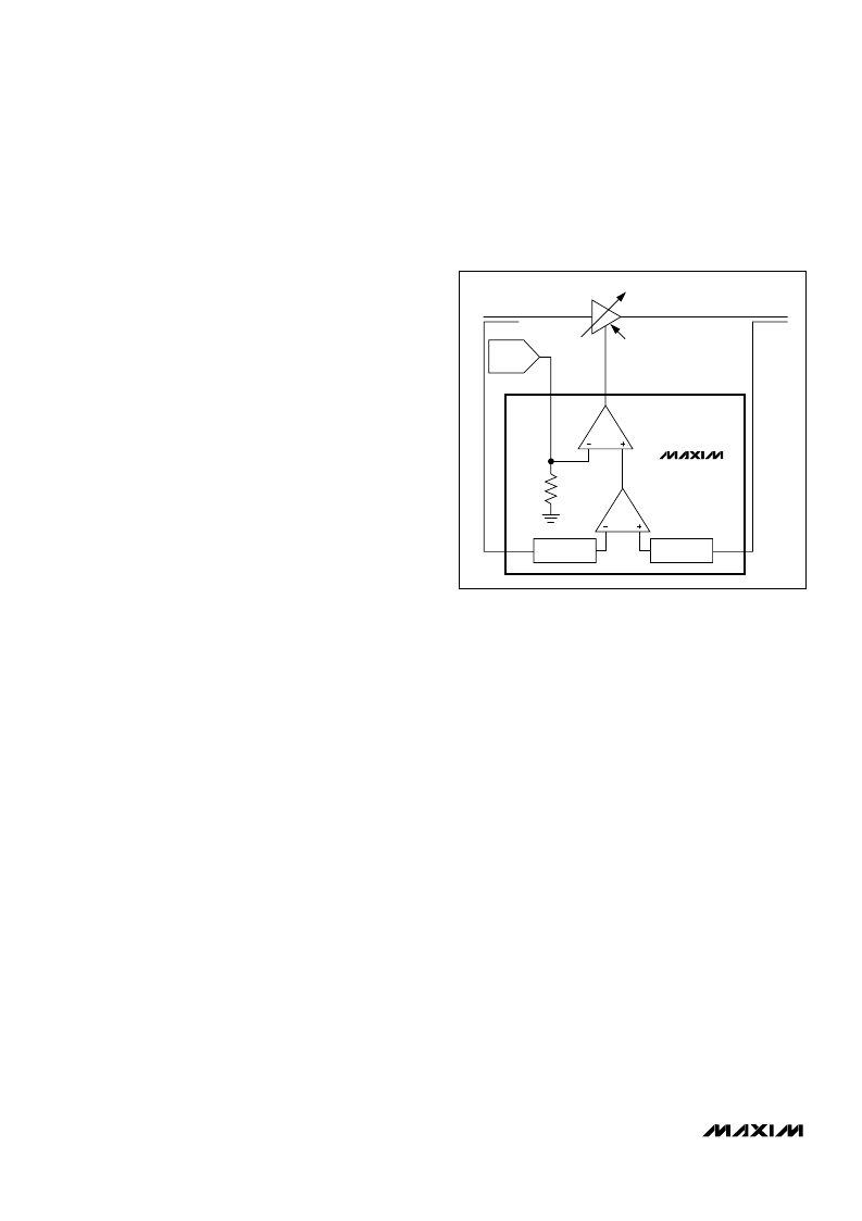
The MAX2016 can be used as a gain controller within
an automatic gain-control (AGC) loop. In the gain-con-
troller mode, remove R3. As shown in
Figure 3, RFINA
and RFINB monitor the VGA’s input and output power
levels, respectively. The MAX2016 produces a DC volt-
age at VOUTD that is proportional to the difference in
these two RF input power levels. An internal op amp
compares the DC voltage with a reference voltage at
SETD. The op amp increases or decreases the voltage
at VOUTD until VOUTD equals to SETD. Thus, the
MAX2016 adjusts the gain of the VGA to a level deter-
mined by the voltage applied to SETD. Operate SETD
between 0.5V and 1.5V for the best dynamic range.
Frequency-Response Modifications
The MAX2016 EV kit has been optimized to support a
minimum operating frequency of 100MHz. However, if
desired, the kit can be modified to operate at a lower
frequency. The EV kit design includes external capaci-
tors (C5 and C12) to lower the frequency operation
below 100MHz. These capacitors should be loaded in
conjunction with changes in the values of C1, C2, C8,
and C9 to lower the input frequency range below
100MHz. Refer to the
Applications Information
section
in the MAX2016 data sheet for the equation to calculate
the required capacitance.
Power-Supply Connection
The MAX2016 is designed to operate from a single
+2.7V to +3.6V supply. To operate under a higher sup-
ply voltage range, a resistor must be connected in
series with the power supply and V
CC
to reduce the
voltage delivered to the chip. For a +4.75V to +5.25V
supply, change R6 to a 37.4
(±1%) resistor.
Layout Considerations
The MAX2016 evaluation board can be a guide for
board layout. Pay close attention to the thermal design
and close placement of the parts to the IC. The
MAX2016 package exposed paddle (EP) conducts heat
from the part and provides a low-impedance electrical
connection. The EP must be attached to the PCB
ground plane with a low thermal and electrical contact.
Ideally, this can be achieved by soldering the backside
package contact directly to a top metal ground plane on
the PCB. Alternatively, the EP can be connected to a
ground plane using an array of plated vias directly
below the EP. The MAX2016 EV kit uses nine equally
spaced, 0.012in-diameter, plated through holes to con-
nect the EP to the lower ground planes.
Keep the input traces carrying RF signals as short as
possible to minimize radiation and insertion loss due to
the PCB. The isolation of the RF inputs is dependent
upon the layout of these traces, which must be physical-
ly isolated from one another for optimum performance.
Each power-supply node on the PCB should have its
own decoupling capacitor. This minimizes supply cou-
pling from one section of the PCB to another. Using a
star topology for the supply layout, in which each power-
supply node in the circuit has a separate connection to
the central node, can further minimize coupling between
sections of the PCB.
MAX2016 Evaluation Kit
4
_______________________________________________________________________________________
MAX2016
LOGARITHMIC
DETECTOR
LOGARITHMIC
DETECTOR
20k
VGA
GAIN-CONTROL INPUT
RFINA
RFINB
OUTD
SETD
VGA INPUT
VGA OUTPUT
SET-POINT
DAC
COUPLER
COUPLER
Figure 3. In the Gain-Controller Mode, the VOUTD Maintains
the Gain of the VGA
相關(guān)PDF資料 |
PDF描述 |
|---|---|
| MAX2021_1 | Evaluation Kit |
| MAX2021EVKIT | Evaluation Kit |
| MAX2022EVKIT | Evaluation Kit |
| MAX2023_1 | Evaluation Kit |
| MAX2023EVKIT | Evaluation Kit |
相關(guān)代理商/技術(shù)參數(shù) |
參數(shù)描述 |
|---|---|
| MAX20-17.0C | 制造商:MDE 制造商全稱:MDE Semiconductor, Inc. 功能描述:HIGH CURRENT TRANSIENT VOLTAGE SUPPRESSOR (TVS) DIODE |
| MAX20-17.0CA | 制造商:MDE 制造商全稱:MDE Semiconductor, Inc. 功能描述:HIGH CURRENT TRANSIENT VOLTAGE SUPPRESSOR (TVS) DIODE |
| MAX20-18.0C | 制造商:MDE 制造商全稱:MDE Semiconductor, Inc. 功能描述:HIGH CURRENT TRANSIENT VOLTAGE SUPPRESSOR (TVS) DIODE |
| MAX20-18.0CA | 制造商:MDE 制造商全稱:MDE Semiconductor, Inc. 功能描述:HIGH CURRENT TRANSIENT VOLTAGE SUPPRESSOR (TVS) DIODE |
| MAX201C/D | 功能描述:RS-232接口集成電路 RoHS:否 制造商:Exar 數(shù)據(jù)速率:52 Mbps 工作電源電壓:5 V 電源電流:300 mA 工作溫度范圍:- 40 C to + 85 C 安裝風(fēng)格:SMD/SMT 封裝 / 箱體:LQFP-100 封裝: |
發(fā)布緊急采購,3分鐘左右您將得到回復(fù)。