- 您現(xiàn)在的位置:買賣IC網(wǎng) > PDF目錄383344 > MAX1984 (Maxim Integrated Products, Inc.) Ultra-High-Efficiency White LED Drivers PDF資料下載
參數(shù)資料
| 型號(hào): | MAX1984 |
| 廠商: | Maxim Integrated Products, Inc. |
| 元件分類: | LED驅(qū)動(dòng)器 |
| 英文描述: | Ultra-High-Efficiency White LED Drivers |
| 中文描述: | 超高效率白光LED驅(qū)動(dòng)器 |
| 文件頁數(shù): | 14/17頁 |
| 文件大?。?/td> | 333K |
| 代理商: | MAX1984 |

M
LED Selection
The MAX1984/MAX1985/MAX1986 provide a control
input (SEL) to selectively turn on one subset, the other
subset, or all of the LEDs. SEL is a three-level logic
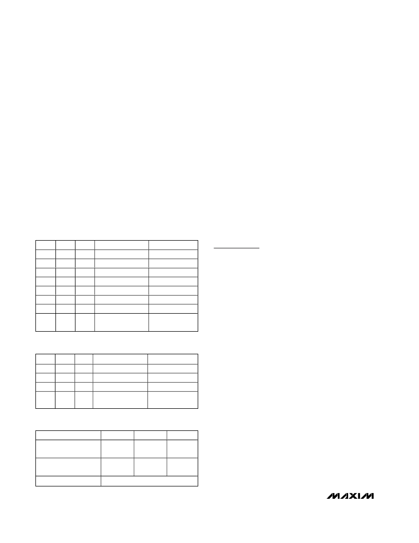
input that can be connected to logic low, logic high, or
left unconnected. Table 5 is the truth table.
LED Test Mode
Connecting SETI to ground enables the LED test mode.
In this mode, the LED current is set to 0.5mA and
DC-to-DC switching is inhibited. OUT is powered from
IN through an internal silicon diode.
Forcing 0.5mA through the LED is a simple way to
determine whether the diode has suffered any ESD
damage. LEDs that do not light in this mode usually
have suffered ESD or other damage. The dimming con-
trol inputs are ignored in the test mode.
Shutdown
As soon as the input voltage rises above the UVLO
threshold and the internal reference is ready, the step-
up regulator starts unless the device is in shutdown. If a
2-bit or 3-bit parallel control is used, the MAX1984/
MAX1985/MAX1986 enter shutdown mode when BITA,
BITB, and BITC are logic low. The parts come out of
shutdown if at least 1 bit is logic high. If DPWM control
is used, the parts enter shutdown mode when the duty
cycle of BITA is less than 5% (typ) and BITC is logic
low. If analog control is used, the parts enter shutdown
when the voltages on both BITA and BITB are logic low.
Overvoltage Protection
Output OVP prevents the internal switches from being
damaged if all LEDs are open. If the output voltage
rises above OUT OVP rising threshold, the
MAX1984/MAX1985/MAX1986 turn off the step-up reg-
ulator. Once the output voltage falls below OVP falling
threshold, the step-up regulator turns on again.
Applications Information
Inductor Selection
The MAX1984/MAX1985/MAX1986
’
s 1MHz switching
frequency allows the use of low-profile surface-mount
inductors. The MAX1984 works well with a 10μH induc-
tor, the MAX1985 works well with a 15μH inductor, and
the MAX1986 works well with a 22μH inductor. The
inductor saturation current rating should be higher than
the N-channel switch current limit. For high efficiency,
choose an inductor made of high-frequency core mate-
rial to reduce core losses. Using a shielded inductor
reduces radiated EMI.
Output Capacitor Selection
The output capacitor affects the circuit
’
s stability and
output-voltage ripple. The MAX1984 works well with a
4.7μF ceramic output capacitor, the MAX1985 works
well with a 3.3μF ceramic output capacitor, and the
MAX1986 works well with a 2.2μF ceramic output
capacitor. Always use capacitors with working voltage
ratings higher than the output OVP rising threshold
(5.5V max).
Ultra-High-Efficiency White
LED Drivers
14
______________________________________________________________________________________
BITA
0
0
0
0
1
1
1
BITB
0
0
1
1
0
0
1
BITC
0
1
0
1
0
1
0
BRIGHTNESS (%)
0
14.3
26.6
42.9
57.1
71.4
85.7
COMMENTS
Shutdown
Minimum current
—
—
—
—
—
1
1
1
100
Full-scale current
set by SETI
Table 3. 3-Bit Parallel Control Truth Table
BITA
0
0
1
BITB
0
1
0
BITC
0
0
0
BRIGHTNESS (%)
0
33.3
66.7
COMMENTS
Shutdown
Minimum current
—
1
1
0
100
Full-scale current
set by SETI
Table 4. 2-Bit Parallel Control Truth Table
SEL
MAX1984
MAX1985
MAX1986
Low (V
SEL
< 0.4V)
LED1 to
LED5 ON
LED1 to
LED4 ON
LED1 to
LED3 ON
Mid (SEL unconnected
or 0.5V < V
SEL
< 1.8V)
High (V
SEL
> 2.05V)
LED6 to
LED8 ON
LED5 to
LED6 ON
LED4 ON
All LEDs ON
Table 5. SEL Control Truth Table
相關(guān)PDF資料 |
PDF描述 |
|---|---|
| MAX1984ETP | Ultra-High-Efficiency White LED Drivers |
| MAX1985ETP | Ultra-High-Efficiency White LED Drivers |
| MAX1986ETE | Ultra-High-Efficiency White LED Drivers |
| MAX1994ETM | Dual Step-Down Controllers Plus Linear- Regulator Controller for Notebook Computers |
| MAX1816 | Replaced by TMS320VC5506 : Digital Signal Processors 144-LQFP |
相關(guān)代理商/技術(shù)參數(shù) |
參數(shù)描述 |
|---|---|
| MAX1984ETP | 功能描述:LED照明驅(qū)動(dòng)器 RoHS:否 制造商:STMicroelectronics 輸入電壓:11.5 V to 23 V 工作頻率: 最大電源電流:1.7 mA 輸出電流: 最大工作溫度: 安裝風(fēng)格:SMD/SMT 封裝 / 箱體:SO-16N |
| MAX1984ETP+ | 功能描述:LED照明驅(qū)動(dòng)器 High-Efficiency White LED Driver RoHS:否 制造商:STMicroelectronics 輸入電壓:11.5 V to 23 V 工作頻率: 最大電源電流:1.7 mA 輸出電流: 最大工作溫度: 安裝風(fēng)格:SMD/SMT 封裝 / 箱體:SO-16N |
| MAX1984ETP+T | 功能描述:LED照明驅(qū)動(dòng)器 High-Efficiency White LED Driver RoHS:否 制造商:STMicroelectronics 輸入電壓:11.5 V to 23 V 工作頻率: 最大電源電流:1.7 mA 輸出電流: 最大工作溫度: 安裝風(fēng)格:SMD/SMT 封裝 / 箱體:SO-16N |
| MAX1984ETP-T | 功能描述:LED照明驅(qū)動(dòng)器 RoHS:否 制造商:STMicroelectronics 輸入電壓:11.5 V to 23 V 工作頻率: 最大電源電流:1.7 mA 輸出電流: 最大工作溫度: 安裝風(fēng)格:SMD/SMT 封裝 / 箱體:SO-16N |
| MAX1985ETP | 功能描述:LED照明驅(qū)動(dòng)器 RoHS:否 制造商:STMicroelectronics 輸入電壓:11.5 V to 23 V 工作頻率: 最大電源電流:1.7 mA 輸出電流: 最大工作溫度: 安裝風(fēng)格:SMD/SMT 封裝 / 箱體:SO-16N |
發(fā)布緊急采購,3分鐘左右您將得到回復(fù)。