- 您現(xiàn)在的位置:買賣IC網(wǎng) > PDF目錄383340 > MAX1909ETI (MAXIM INTEGRATED PRODUCTS INC) Multichemistry Battery Charger with Automatic System Power Selector PDF資料下載
參數(shù)資料
| 型號: | MAX1909ETI |
| 廠商: | MAXIM INTEGRATED PRODUCTS INC |
| 元件分類: | 電源管理 |
| 英文描述: | Multichemistry Battery Charger with Automatic System Power Selector |
| 中文描述: | 2-CHANNEL POWER SUPPLY SUPPORT CKT, QCC28 |
| 封裝: | 5 X 5 MM, 0.80 MM HEIGHT, MO-220-WHHD-1, TQFN-28 |
| 文件頁數(shù): | 27/29頁 |
| 文件大小: | 551K |
| 代理商: | MAX1909ETI |
第1頁第2頁第3頁第4頁第5頁第6頁第7頁第8頁第9頁第10頁第11頁第12頁第13頁第14頁第15頁第16頁第17頁第18頁第19頁第20頁第21頁第22頁第23頁第24頁第25頁第26頁當前第27頁第28頁第29頁

M
Multichemistry Battery Charger with Automatic
System Power Selector
______________________________________________________________________________________
27
As such, both capacitance and ESR are important
parameters in specifying the output capacitor as a filter
and to ensure the stability of the DC-to-DC converter.
(See the
Compensation
section.) Beyond the stability
requirements, it is often sufficient to make sure that the
output capacitor
’
s ESR is much lower than the battery
’
s
ESR. Either tantalum or ceramic capacitors can be
used on the output. Ceramic devices are preferable
because of their good voltage ratings and resilience to
surge currents.
Applications Information
Startup Conditioning Charge for
Overdischarged Cells
It is desirable to charge deeply discharged batteries at
a low rate to improve cycle life. The MAX1909 automati-
cally reduces the charge current when the voltage per
cell is below 3.1V. The charge current-sense voltage is
set to 4.5mV (I
CHG
= 300mA with RS2 = 15m
) until
the battery voltage rises above the threshold. There is
approximately 300mV for 3 cell, 400mV for 4 cell of hys-
teresis to prevent the charge current magnitude from
chattering between the two values.
Thermal Charge Qualification
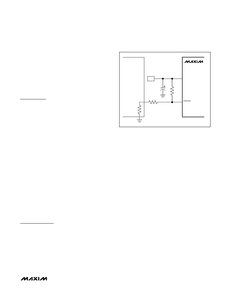
Based on the cell characteristics, the MAX1909 should
not charge batteries operating above a specified
temperature. Often a PTC thermistor is included inside
the battery pack to measure its temperature. When
connected to the charger, the thermistor forms a voltage-
divider with a resistive pullup to the LDO. The threshold
voltage of
PKPRES
is 90% of V
LDO
(typ), with hysteresis
of 1% of V
LDO
to prevent erratic transitions. The thermis-
tor can be selected to have a resistance vs. temperature
characteristic that abruptly increases above a critical
temperature. This arrangement automatically shuts down
the MAX1909 when the battery pack is above a critical
temperature. For the example shown in Figure 12, a
Thermometrics YSC060 device is selected with the ther-
mal threshold of approximately +60
°
C.
Layout and Bypassing
Bypass DCIN with a 1μF capacitor to ground (Figure 1).
D4 protects the MAX1909 when the DC power source
input is reversed. A signal diode for D4 is adequate
because DCIN only powers the LDO and the internal
reference. Bypass LDO, DHIV, DLOV, and other pins
as shown in Figure 1.
Good PC board layout is required to achieve specified
noise, efficiency, and stable performance. The PC
board layout artist must be given explicit instructions
—
preferably, a sketch showing the placement of the
power-switching components and high-current routing.
Refer to the PC board layout in the MAX1909 evaluation
kit for examples. A ground plane is essential for opti-
mum performance. In most applications, the circuit is
located on a multilayer board, and full use of the four or
more copper layers is recommended. Use the top layer
for high-current connections, the bottom layer for quiet
connections, and the inner layers for an uninterrupted
ground plane.
Use the following step-by-step guide:
1) Place the high-power connections first, with their
grounds adjacent:
a) Minimize the current-sense resistor trace
lengths, and ensure accurate current sensing
with Kelvin connections.
b) Minimize ground trace lengths in the high-current
paths.
c) Minimize other trace lengths in the high-current
paths.
d) Use > 5mm wide traces.
e) Connect C1 and C2 to the high-side MOSFET
(10mm max length). Return these capacitors to
the power ground plane.
f) Minimize the LX node (MOSFETs, rectifier cath-
ode, inductor (15mm max length)).
Ideally, surface-mount power components are
flush against one another with their ground
terminals almost touching. These high-current
grounds are then connected to each other with
MAX1909
LDO
CLDO
1
μ
F
R1
10k
LDO
PKPRES
R2
70k
TEMP
THERMISTER
BATTERY
Figure 12. Use of a PTC Thermistor for Thermal Change
Qualification
相關PDF資料 |
PDF描述 |
|---|---|
| MAX190AENG | Low-Power, 12-Bit Sampling ADCs with Internal Reference and Power-Down |
| MAX191BMRG | Low-Power, 12-Bit Sampling ADCs with Internal Reference and Power-Down |
| MAX190 | Low-Power, 12-Bit Sampling ADCs with Internal Reference and Power-Down |
| MAX190BENG | Low-Power, 12-Bit Sampling ADCs with Internal Reference and Power-Down |
| MAX191BENG | Low-Power, 12-Bit Sampling ADCs with Internal Reference and Power-Down |
相關代理商/技術參數(shù) |
參數(shù)描述 |
|---|---|
| MAX1909ETI+ | 功能描述:電池管理 Multichemistry Battery Chargers RoHS:否 制造商:Texas Instruments 電池類型:Li-Ion 輸出電壓:5 V 輸出電流:4.5 A 工作電源電壓:3.9 V to 17 V 最大工作溫度:+ 85 C 最小工作溫度:- 40 C 封裝 / 箱體:VQFN-24 封裝:Reel |
| MAX1909ETI+T | 功能描述:電池管理 Multichemistry Battery Chargers RoHS:否 制造商:Texas Instruments 電池類型:Li-Ion 輸出電壓:5 V 輸出電流:4.5 A 工作電源電壓:3.9 V to 17 V 最大工作溫度:+ 85 C 最小工作溫度:- 40 C 封裝 / 箱體:VQFN-24 封裝:Reel |
| MAX1909ETI-T | 功能描述:電池管理 RoHS:否 制造商:Texas Instruments 電池類型:Li-Ion 輸出電壓:5 V 輸出電流:4.5 A 工作電源電壓:3.9 V to 17 V 最大工作溫度:+ 85 C 最小工作溫度:- 40 C 封裝 / 箱體:VQFN-24 封裝:Reel |
| MAX1909EVKIT | 功能描述:電池管理 Evaluation Kit for the MAX1909 RoHS:否 制造商:Texas Instruments 電池類型:Li-Ion 輸出電壓:5 V 輸出電流:4.5 A 工作電源電壓:3.9 V to 17 V 最大工作溫度:+ 85 C 最小工作溫度:- 40 C 封裝 / 箱體:VQFN-24 封裝:Reel |
| MAX190ACNG | 功能描述:模數(shù)轉換器 - ADC RoHS:否 制造商:Texas Instruments 通道數(shù)量:2 結構:Sigma-Delta 轉換速率:125 SPs to 8 KSPs 分辨率:24 bit 輸入類型:Differential 信噪比:107 dB 接口類型:SPI 工作電源電壓:1.7 V to 3.6 V, 2.7 V to 5.25 V 最大工作溫度:+ 85 C 安裝風格:SMD/SMT 封裝 / 箱體:VQFN-32 |
發(fā)布緊急采購,3分鐘左右您將得到回復。