- 您現(xiàn)在的位置:買賣IC網(wǎng) > PDF目錄296460 > MADS-001317-1320AG SILICON, mm WAVE BAND, MIXER DIODE PDF資料下載
參數(shù)資料
| 型號: | MADS-001317-1320AG |
| 元件分類: | 參考電壓二極管 |
| 英文描述: | SILICON, mm WAVE BAND, MIXER DIODE |
| 文件頁數(shù): | 3/3頁 |
| 文件大小: | 145K |
| 代理商: | MADS-001317-1320AG |
North America Tel: 800.366.2266 / Fax: 978.366.2266
Europe Tel: 44.1908.574.200 / Fax: 44.1908.574.300
Asia/Pacific Tel: 81.44.844.8296 / Fax: 81.44.844.8298
Visit www.macom.com for additional data sheets and product information.
M/A-COM Inc. and its affiliates reserve the right to make changes to the product(s) or
information contained herein without notice.
3
GaAs Solder Bump Flip Chip Schottky Diode
M/A-COM Products
Rev. V2
MADS-001317-1320AG
ADVANCED: Data Sheets contain information regarding a product M/A-COM is considering for
development. Performance is based on target specifications, simulated results, and/or prototype
measurements. Commitment to develop is not guaranteed.
PRELIMINARY: Data Sheets contain information regarding a product M/A-COM has under develop-
ment. Performance is based on engineering tests. Specifications are typical. Mechanical outline has
been fixed. Engineering samples and/or test data may be available. Commitment to produce in
volume is not guaranteed.
Device Installation Procedures
The following guidelines should be observed to avoid damaging GaAs Flip-Chips.
Cleanliness
These devices should be handled in a clean environment. Do not attempt to clean die after installation.
Static Sensitivity
Gallium Arsenide Schottky diodes are ESD sensitive and can be damaged by static electricity. Since Schottky
diodes are rated as Class 0, proper ESD techniques should be used when handling these devices.
General Handling
These devices have a polymer layer which provides scratch protection for the junction area and the anode air
bridge. Die can be handled with plastic tweezers or picked and placed automatically with a #27 tip vacuum pen-
cil.
Assembly Requirements using Tin Lead Solder
This Flip Chip Diode employs a 6 m thick, Sn 63/Pb 37 Solderable interface as part of the 50 m high solder
bump. These chips are designed to be soldered onto hard or soft substrates with the junction side down. They
should be mounted onto silkscreened circuits using 60/40 Sn/Pb solder paste. A typical profile for a Sn 63/Pb
37soldering process is provided in Application Note, M538 Surface Mounting Instructions on the M/A-COM web-
site www.macom.com
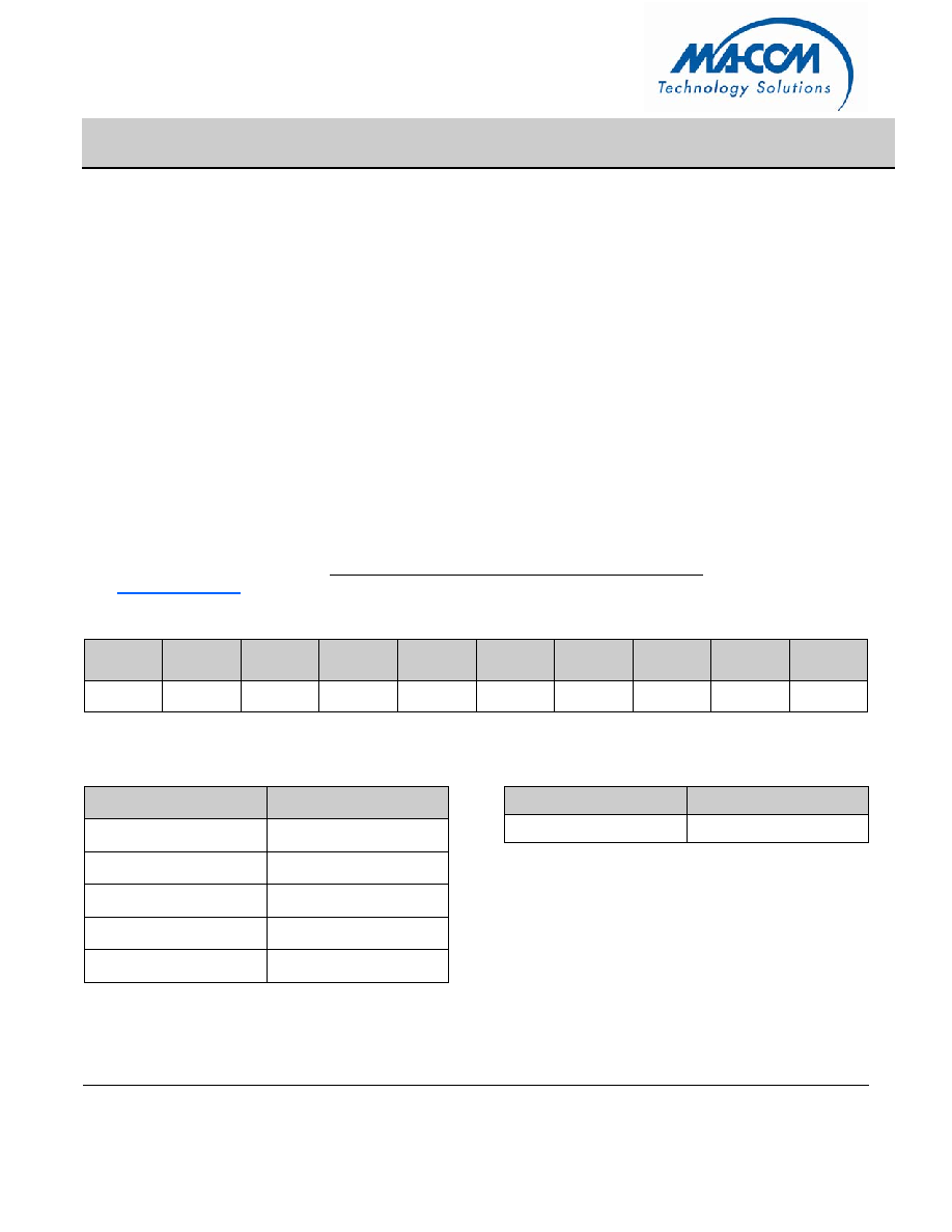
Typical Spice Parameters
Is
(A)
Rs
()
N
Ct0
(pF)
M
Ik
(A)
Vj
(V)
FC
BV
(V)
IBV
(A)
1.7 E-14
4.6
1.08
.047
.38
.016
.86
.99
7
1.0 E-5
Absolute Maximum Ratings @ 25°C 2
Parameter
Maximum Ratings
Operating Temperature
-65°C to +125°C
Storage Temperature
-65°C to +150°C
Incident LO Power
+20 dBm
Incident RF Power
+20 dBm
Mounting Temperature
+300°C for 10 seconds.
Ordering Information
Part Number
Packaging
MADS-001317-1320AG
Gel Pack
2. Exceeding these limits may cause permanent damage.
相關(guān)PDF資料 |
PDF描述 |
|---|---|
| MAIA-007150-0001TR | RF/MICROWAVE MODULATOR |
| MAMXES0068 | 10 MHz - 2000 MHz RF/MICROWAVE DOUBLE BALANCED MIXER, 8.5 dB CONVERSION LOSS-MAX |
| MAN3G10 | 7 SEG NUMERIC DISPLAY, GREEN, 7.62 mm |
| MAN59305 | 7 SEG NUMERIC DISPLAY, HIGH EFFICIENCY RED, 7.62 mm |
| MAN6940E | 7 SEG NUMERIC DISPLAY, HIGH EFFICIENCY RED, 14.22 mm |
相關(guān)代理商/技術(shù)參數(shù) |
參數(shù)描述 |
|---|---|
| MADS-001317-1500 | 制造商:MACOM 制造商全稱:Tyco Electronics 功能描述:Solderable GaAs Flip Chip Schottky Diode |
| MADS-001317-1500AG | 制造商:M/A-COM Technology Solutions 功能描述:Ct=.045pF Rs=7 Ohm To 80GHz 制造商:M/A-COM Technology Solutions 功能描述:Diode Schottky 7V 2-Pin Case 1500 |
| MADS-001317-1500AP | 制造商:MACOM 制造商全稱:Tyco Electronics 功能描述:Solderable GaAs Flip Chip Schottky Diode |
| MADS-001338-12790T | 功能描述:肖特基二極管與整流器 RoHS:否 制造商:Skyworks Solutions, Inc. 產(chǎn)品:Schottky Diodes 峰值反向電壓:2 V 正向連續(xù)電流:50 mA 最大浪涌電流: 配置:Crossover Quad 恢復(fù)時間: 正向電壓下降:370 mV 最大反向漏泄電流: 最大功率耗散:75 mW 工作溫度范圍:- 65 C to + 150 C 安裝風(fēng)格:SMD/SMT 封裝 / 箱體:SOT-143 封裝:Reel |
| MADS001339-1279 | 制造商:M/A-COM Technology Solutions 功能描述:RF SCHOTTKY DIODE |
發(fā)布緊急采購,3分鐘左右您將得到回復(fù)。