- 您現(xiàn)在的位置:買賣IC網(wǎng) > PDF目錄30796 > MAD1105E3 (MICROSEMI CORP-SCOTTSDALE) UNIDIRECTIONAL, 8 ELEMENT, SILICON, TVS DIODE PDF資料下載
參數(shù)資料
| 型號: | MAD1105E3 |
| 廠商: | MICROSEMI CORP-SCOTTSDALE |
| 元件分類: | TVS二極管 - 瞬態(tài)電壓抑制 |
| 英文描述: | UNIDIRECTIONAL, 8 ELEMENT, SILICON, TVS DIODE |
| 封裝: | ROHS COMPLIANT, PLASTIC, DIP-14 |
| 文件頁數(shù): | 1/2頁 |
| 文件大?。?/td> | 80K |
| 代理商: | MAD1105E3 |
Switching Diode Array
Steering Diode TVS Array
WWW
.Microse
m
i
.CO
M
S C O T TS DALE DIVISION
MAD1105 and MAD1105e3
MAD1105,
e3
DESCRIPTION
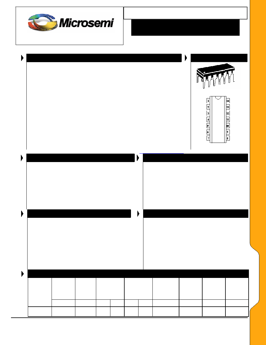
APPEARANCE
These low capacitance diode arrays are multiple, discrete, isolated junctions
fabricated by a planar process and mounted in a 14-pin package for use as
steering diodes protecting up to eight I/O ports from positive ESD, EFT, or
surge by directing them to the positive side of the power supply (pin 14)*. An
external TVS diode may be added between the positive supply line and
ground to prevent overvoltage on the supply rail. They may also be used in
fast switching core-driver applications. This includes computers and peripheral
equipment such as magnetic cores, thin-film memories, plated-wire memories,
etc., as well as decoding or encoding applications. These arrays offer many
advantages of integrated circuits such as high-density packaging and
improved reliability.
This is a result of fewer pick and place operations,
smaller footprint, smaller weight, and elimination of various discrete packages
that may not be as user friendly in PC board mounting. They are available
with either Tin-Lead plating terminations or as RoHS Compliant with annealed
matte-Tin finish by adding an “e3” suffix to the part number.
*See MAD1106(e3) for directing negative transients to ground.
Top Viewing Pin Layout
IMPORTANT: For the most current data, consult MICROSEMI’s website: http://www.microsemi.com
FEATURES
APPLICATIONS / BENEFITS
8 Diode Array
Molded 14-Pin Dual-In-Line Package
UL 94V-0 Flammability Classification
Low Capacitance 1.5 pF per diode
Switching speeds less than 5 ns
RoHS Compliant devices available by adding “e3” suffix
IEC 61000-4 compatible
61000-4-2 (ESD): Air 15kV, contact – 8 kV
61000-4-4 (EFT): 40A – 5/50 ns
61000-4-5 (surge): 12A, 8/20
s
Low capacitance steering diode protection for high
frequency data lines
RS-232 & RS-422 Interface Networks
Ethernet: 10 Base T
Computer I / O Ports
LAN
Switching Core Drivers
MAXIMUM RATINGS
MECHANICAL AND PACKAGING
Operating Temperature: -55°C to +150°C
Storage Temperature: -55°C to +150°C
Forward Surge Current: 2 Amps (8.3 ms)
12 Amps (8/20
s)
Continuous Forward Current: 400 mA (one diode)
Power Dissipation (P
D): 1500 mW (total)
Solder temperatures: 260°C for 10 s (maximum)
CASE: Void-free transfer molded thermosetting
epoxy body meeting UL94V-0 flammability
classification
TERMINALS: Tin-Lead or RoHS Compliant
annealed matte-Tin plating solderable per MIL-STD-
750 method 2026
MARKING: MSC logo, MAD1105 or MAD1105e3
and date code. Pin #1 is to the left of the dot or
indent on top of package.
WEIGHT: 0.997 grams (approximate)
Carrier tubes: 25 pcs (Standard)
ELECTRICAL CHARACTERISTICS PER LINE @ 25°C Unless otherwise specified
BREAKDOWN
VOLTAGE
VBR
@ IBR =100A
V
WORKING
PEAK
REVERSE
VOLTAGE
VRWM
V
LEAKAGE
CURRENT
IR
TA = 25°C
A
LEAKAGE
CURRENT
IR
TA = 150°C
A
CAPACITANCE
C
@ 0 V
pF
REVERSE
RECOVERY
TIME
trr
ns
FORWARD
VOLTAGE
VF
IF = 10 mA
V
FORWARD
VOLTAGE
VF
IF = 100 mA
V
PART
NUMBER
MIN
MAX
@VR
MAX
@VR
TYP
MAX
MAD1105
MAD1105e3
90
75
0.200
20
300
20
1.5
5.0
1.00
1.20
Microsemi
Scottsdale Division
Page 1
Copyright
2005
6-28-2005 REV L
8700 E. Thomas Rd. PO Box 1390, Scottsdale, AZ 85252 USA, (480) 941-6300, Fax: (480) 947-1503
相關(guān)PDF資料 |
PDF描述 |
|---|---|
| MADP-000235-10720T | SILICON, PIN DIODE |
| MADP-000910-13050T | GALLIUM ARSENIDE, PIN DIODE |
| MALM062H | 6.2 V, 0.15 W, SILICON, UNIDIRECTIONAL VOLTAGE REGULATOR DIODE |
| MALS180XG | 18.75 V, 0.15 W, SILICON, UNIDIRECTIONAL VOLTAGE REGULATOR DIODE |
| MAP4KE10ATR | 400 W, UNIDIRECTIONAL, SILICON, TVS DIODE, DO-204AL |
相關(guān)代理商/技術(shù)參數(shù) |
參數(shù)描述 |
|---|---|
| MAD1105E3/TU | 制造商:Microsemi Corporation 功能描述:8 DIODES, 8 LINES, IF=400MA, VBR=90V - Bulk 制造商:Microsemi Corporation 功能描述:DIODE ARRAY 400MA 90V 14DIP |
| MAD1106 | 制造商:PROTEC 制造商全稱:Protek Devices 功能描述:STEERING DIODE ARRAY |
| MAD1106_05 | 制造商:MICROSEMI 制造商全稱:Microsemi Corporation 功能描述:Switching Diode Array Steering Diode TVS ArrayTM |
| MAD1106E3 | 制造商:MICROSEMI 制造商全稱:Microsemi Corporation 功能描述:Switching Diode Array Steering Diode TVS ArrayTM |
| MAD1106E3/TU | 制造商:Microsemi Corporation 功能描述:8 DIODES, 8 LINES, IF=400MA, VBR=90V - Bulk 制造商:Microsemi Corporation 功能描述:DIODE ARRAY 400MA 90V 14DIP |
發(fā)布緊急采購,3分鐘左右您將得到回復(fù)。