- 您現(xiàn)在的位置:買賣IC網(wǎng) > PDF目錄45048 > M38C89MF-XXXFP 8-BIT, MROM, 4 MHz, MICROCONTROLLER, PQFP144 PDF資料下載
參數(shù)資料
| 型號(hào): | M38C89MF-XXXFP |
| 元件分類: | 微控制器/微處理器 |
| 英文描述: | 8-BIT, MROM, 4 MHz, MICROCONTROLLER, PQFP144 |
| 封裝: | 20 X 20 MM, 0.50 MM PITCH, PLASTIC, LQFP-144 |
| 文件頁(yè)數(shù): | 35/55頁(yè) |
| 文件大小: | 981K |
| 代理商: | M38C89MF-XXXFP |
第1頁(yè)第2頁(yè)第3頁(yè)第4頁(yè)第5頁(yè)第6頁(yè)第7頁(yè)第8頁(yè)第9頁(yè)第10頁(yè)第11頁(yè)第12頁(yè)第13頁(yè)第14頁(yè)第15頁(yè)第16頁(yè)第17頁(yè)第18頁(yè)第19頁(yè)第20頁(yè)第21頁(yè)第22頁(yè)第23頁(yè)第24頁(yè)第25頁(yè)第26頁(yè)第27頁(yè)第28頁(yè)第29頁(yè)第30頁(yè)第31頁(yè)第32頁(yè)第33頁(yè)第34頁(yè)當(dāng)前第35頁(yè)第36頁(yè)第37頁(yè)第38頁(yè)第39頁(yè)第40頁(yè)第41頁(yè)第42頁(yè)第43頁(yè)第44頁(yè)第45頁(yè)第46頁(yè)第47頁(yè)第48頁(yè)第49頁(yè)第50頁(yè)第51頁(yè)第52頁(yè)第53頁(yè)第54頁(yè)第55頁(yè)
39
SINGLE-CHIP 8-BIT CMOS MICROCOMPUTER
MITSUBISHI MICROCOMPUTERS
38C8 Group
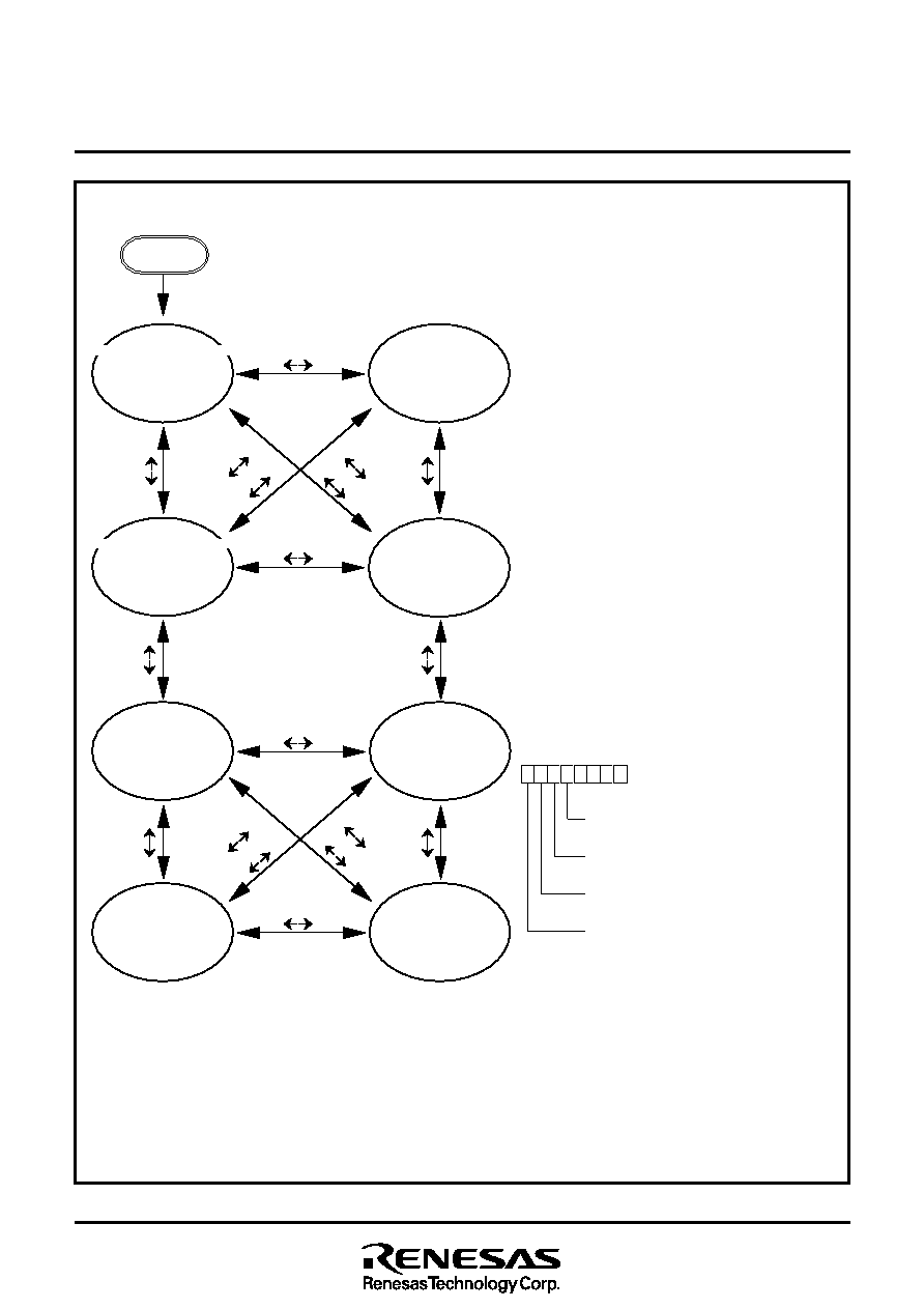
Fig. 39 State transitions of system clock
Low-speed mode (f(
φ) =16 kHz)
Notes 1 : Switch the mode by the allows shown between the mode blocks. (Do not switch between the mode directly without an allow.)
2 : The all modes can be switched to the stop mode or the wait mode and returned to the source mode when the stop mode or the wait mode is ended.
3 : Timer and LCD operate in the wait mode.
4 : When the stop mode is ended, a delay of approximately 1 ms occurs automatically by timer 1 and timer 2 in middle-/high-speed mode.
5 : When the stop mode is ended, a delay of approximately 0.25 s occurs automatically by timer 1 and timer 2 in low-speed mode.
6 : Wait until oscillation stabilizes after oscillating the main clock XIN before the switching from the low-speed mode to middle-/high-speed mode.
7 : The example assumes that 4 MHz is being applied to the XIN pin and 32 kHz to the XCIN pin.
φ indicates the internal clock.
CM4 : Sub-clock (XCIN –XCOUT) oscillating bit
0: Stopped
1: Oscillating
CM5 : Main clock (XIN–XOUT) stop bit
0: Oscillating
1: Stopped
CM6 : Main clock division ratio selection bit
0: f(XIN)/2 (high-speed mode)
1: f(XIN)/8 (middle-speed mode)
CM7 : Internal system clock selection bit
0: XIN–XOUT selected
(middle-/high-speed mode)
1: XCIN–XCOUT selected
(low-speed mode)
CPU mode register
(CPUM : address 003B16)
b7
b4
Reset
CM6
“0”
“1”
C
M
4
“0
”
“1
”
Middle-speed mode (f(
φ) = 0.5 MHz)
Middle-speed mode (f(
φ) = 0.5 MHz)
High-speed mode (f(
φ) = 2 MHz)
High-speed mode (f(
φ) = 2 MHz)
Low-speed mode (f(
φ) = 16 kHz)
Low-speed mode (f(
φ) =16 kHz)
Low-speed mode (f(
φ) =16 kHz)
CM6
“0”
“1”
CM6
“0”
“1”
CM6
“0”
“1”
C
M
4
“0
”
“1
”
C
M
7
“0
”
“1
”
C
M
7
“0
”
“1
”
C
M
5
“0
”
“1
”
C
M
5
“0
”
“1
”
CM7 = 0 (4 MHz selected)
CM6 = 1 (Middle-speed)
CM5 = 0 (4 MHz oscillating)
CM4 = 0 (32 kHz stoped)
CM7 = 0 (4 MHz selected)
CM6 = 0 (High-speed)
CM5 = 0 (4 MHz oscillating)
CM4 = 0 (32 kHz stoped)
CM7 = 0 (4 MHz selected)
CM6 = 1 (Middle-speed)
CM5 = 0 (4 MHz oscillating)
CM4 = 1 (32 kHz oscillating)
CM7 = 0 (4 MHz selected)
CM6 = 0 (High-speed)
CM5 = 0 (4 MHz oscillating)
CM4 = 1 (32 kHz oscillating)
CM7 = 1 (32 kHz selected)
CM6 = 0 (High-speed)
CM5 = 0 (4 MHz oscillating)
CM4 = 1 (32 kHz oscillating)
CM7 = 1 (32 kHz selected)
CM6 = 1 (Middle-speed)
CM5 = 0 (4 MHz oscillating)
CM4 = 1 (32 kHz oscillating)
CM7 = 1 (32 kHz selected)
CM6 = 1 (Middle-speed)
CM5 = 1 (4 MHz stopped)
CM4 = 1 (32 kHz oscillating)
CM7 = 1 (32 kHz selected)
CM6 = 0 (High-speed)
CM5 = 1 (4 MHz stopped)
CM4 = 1 (32 kHz oscillating)
C
M
4
“0
”
“1
”
C
M
6
“0
”
“1
”
C
M
5
“0
”
“1
”
C
M
6
“0
”
“1
”
C
M
6
“0
”
“1
”
C
M
4
“1
”
“0
”
C
M
6
“0
”
“1
”
C
M
5
“1
”
“0
”
相關(guān)PDF資料 |
PDF描述 |
|---|---|
| M38C89EFFP | 8-BIT, OTPROM, 4 MHz, MICROCONTROLLER, PQFP144 |
| M38D24G6HP | 8-BIT, FLASH, 6.25 MHz, MICROCONTROLLER, PQFP64 |
| M38D24G4FP | 8-BIT, FLASH, 6.25 MHz, MICROCONTROLLER, PQFP64 |
| M38D24G4-XXXHP | 8-BIT, FLASH, 6.25 MHz, MICROCONTROLLER, PQFP64 |
| M38D28G8HP | 8-BIT, FLASH, 6.25 MHz, MICROCONTROLLER, PQFP64 |
相關(guān)代理商/技術(shù)參數(shù) |
參數(shù)描述 |
|---|---|
| M38D20F1XXXFP | 制造商:RENESAS 制造商全稱:Renesas Technology Corp 功能描述:SINGLE-CHIP 8-BIT CMOS MICROCOMPUTER |
| M38D20F1XXXHP | 制造商:RENESAS 制造商全稱:Renesas Technology Corp 功能描述:SINGLE-CHIP 8-BIT CMOS MICROCOMPUTER |
| M38D20F2XXXFP | 制造商:RENESAS 制造商全稱:Renesas Technology Corp 功能描述:SINGLE-CHIP 8-BIT CMOS MICROCOMPUTER |
| M38D20F2XXXHP | 制造商:RENESAS 制造商全稱:Renesas Technology Corp 功能描述:SINGLE-CHIP 8-BIT CMOS MICROCOMPUTER |
| M38D20F3XXXFP | 制造商:RENESAS 制造商全稱:Renesas Technology Corp 功能描述:SINGLE-CHIP 8-BIT CMOS MICROCOMPUTER |
發(fā)布緊急采購(gòu),3分鐘左右您將得到回復(fù)。