- 您現(xiàn)在的位置:買賣IC網 > PDF目錄98006 > M37510E6-FS 8-BIT, UVPROM, 8 MHz, MICROCONTROLLER, CQCC160 PDF資料下載
參數(shù)資料
| 型號: | M37510E6-FS |
| 元件分類: | 微控制器/微處理器 |
| 英文描述: | 8-BIT, UVPROM, 8 MHz, MICROCONTROLLER, CQCC160 |
| 封裝: | WINDOWED, GLASS SEALED, LCC-160 |
| 文件頁數(shù): | 22/43頁 |
| 文件大小: | 614K |
| 代理商: | M37510E6-FS |
第1頁第2頁第3頁第4頁第5頁第6頁第7頁第8頁第9頁第10頁第11頁第12頁第13頁第14頁第15頁第16頁第17頁第18頁第19頁第20頁第21頁當前第22頁第23頁第24頁第25頁第26頁第27頁第28頁第29頁第30頁第31頁第32頁第33頁第34頁第35頁第36頁第37頁第38頁第39頁第40頁第41頁第42頁第43頁
29
7510 Group
SINGLE-CHIP 8-BIT CMOS MICROCOMPUTER
MITSUBISHI MICROCOMPUTERS
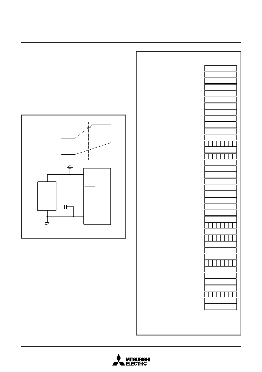
RESET CIRCUIT
To reset the microcomputer, RESET pin should be held at “L” level
for 2
s or more. Then RESET pin is returned to “H” level (the
power source voltage should be between 2.5 V and 5.5 V, and XIN
oscillation width is stable), reset is released. In order to give the
XIN clock time to stabilize, internal operation does not begin until
after about 8000 XIN clock cycles are complete. After the reset is
completed, the program starts from the address contained in ad-
dress FFFD16 (high-order) and address FFFC16 (low-order).
Make sure that the reset input voltage is less than 0.5 V for VCC of
3.0 V at f(XIN) = 8.0 MHz.
Fig. 26 Example of reset circuit
Fig. 27 Internal status of microcomputer after reset
Power source
voltage 0V
Poweron
3.0V
Reset input
voltage 0V
0.5V
VCC
RESET
VSS
7510 group
f(XIN) = 8.0MHz
3
1
5
4
0.1
F
M51953AL
100000 00
001916
(13) Serial I/O1 status register
0016
001116
(12) Port P5 pull-up control register
0016
001016
(11) Port P4 pull-up control register
0016
000E16
(9) Port P2 pull-up control register
0016
000D16
(8) Port P1 pull-up control register
0016
000C16
(7) Port P0 pull-up control register
0016
000B16
(6) Port P5 direction register
0016
000916
(5) Port P4 direction register
0016
000716
(4) Port P3 direction register
0016
000516
(3) Port P2 direction register
0016
000316
(2) Port P1 direction register
0016
000116
(1) Port P0 direction register
0016
000F16
(10) Port P3 pull-up control register
0016
001A16
(14) Serial I/O1 control register
111000 00
001B16
(15) UART1 control register
FF16
002016
(16) Timer X (low)
FF16
002116
(17) Timer X (high)
FF16
002216
(18) Timer Y (low)
FF16
002316
(19) Timer Y (high)
FF16
002416
(20) Timer 1
0116
002516
(21) Timer 2
FF16
002616
(22) Timer 3
0016
002716
(23) Timer X mode register
0016
002816
(24) Timer Y mode register
0016
002916
(25) Timer 123 mode register
100000 00
003116
(26) Serial I/O2 status register
0016
003216
(27) Serial I/O2 control register
111000 00
003316
(28) UART2 control register
0016
003716
(29) LCD contrast control register
0016
003916
(30) LCD mode register
0016
003A16
(31) Interrupt edge selection register
010011 00
003B16
(32) CPU mode register
0016
003C16
(33) Interrupt request register 1
0016
003D16
(34) Interrupt request register 2
0016
003E16
(35) Interrupt control register 1
0016
003F16
(36) Interrupt control register 2
!!!!! 1 !!
(PS)
(37) Processor status register
Contents of address
FFFD 16
(PCH)
(38) Program counter
Contents of address
FFFC 16
(PCL)
The contents of all other registers and RAM are undefined after
reset, so they must be initialized by software.
! : Undefined
Note :
Register contents
Address
相關PDF資料 |
PDF描述 |
|---|---|
| M37510E6-XXXFP | 8-BIT, OTPROM, 4 MHz, MICROCONTROLLER, PQFP176 |
| M37516M6H-XXXKP | 8-BIT, MROM, 4 MHz, MICROCONTROLLER, PQFP44 |
| M37516M4H-XXXKP | 8-BIT, MROM, 4 MHz, MICROCONTROLLER, PQFP44 |
| M37516M6H-XXXKP | 8-BIT, MROM, 4 MHz, MICROCONTROLLER, PQFP44 |
| M37532E8FP | 8-BIT, OTPROM, 6 MHz, MICROCONTROLLER, PDSO36 |
相關代理商/技術參數(shù) |
參數(shù)描述 |
|---|---|
| M37510E7156FP | 制造商:MITSUBISHI 制造商全稱:Mitsubishi Electric Semiconductor 功能描述:SINGLE-CHIP 8-BIT CMOS MICROCOMPUTER |
| M37510E8156FP | 制造商:MITSUBISHI 制造商全稱:Mitsubishi Electric Semiconductor 功能描述:SINGLE-CHIP 8-BIT CMOS MICROCOMPUTER |
| M37510M1156FP | 制造商:MITSUBISHI 制造商全稱:Mitsubishi Electric Semiconductor 功能描述:SINGLE-CHIP 8-BIT CMOS MICROCOMPUTER |
| M37510M2156FP | 制造商:MITSUBISHI 制造商全稱:Mitsubishi Electric Semiconductor 功能描述:SINGLE-CHIP 8-BIT CMOS MICROCOMPUTER |
| M37510M3156FP | 制造商:MITSUBISHI 制造商全稱:Mitsubishi Electric Semiconductor 功能描述:SINGLE-CHIP 8-BIT CMOS MICROCOMPUTER |
發(fā)布緊急采購,3分鐘左右您將得到回復。