- 鎮ㄧ従鍦ㄧ殑浣嶇疆锛�璨疯常IC缍� > PDF鐩寗4365 > M1AFS1500-2FG676I (Microsemi SoC)IC FPGA 8MB FLASH 1.5M 676-FBGA PDF璩囨枡涓嬭級
鍙冩暩璩囨枡
| 鍨嬭櫉锛� | M1AFS1500-2FG676I |
| 寤犲晢锛� | Microsemi SoC |
| 鏂囦欢闋佹暩锛� | 281/334闋� |
| 鏂囦欢澶�?銆�?/td> | 0K |
| 鎻忚堪锛� | IC FPGA 8MB FLASH 1.5M 676-FBGA |
| 妯欐簴鍖呰锛� | 40 |
| 绯诲垪锛� | Fusion® |
| RAM 浣嶇附瑷堬細 | 276480 |
| 杓稿叆/杓稿嚭鏁革細 | 252 |
| 闁€鏁革細 | 1500000 |
| 闆绘簮闆诲锛� | 1.425 V ~ 1.575 V |
| 瀹夎椤炲瀷锛� | 琛ㄩ潰璨艰 |
| 宸ヤ綔婧害锛� | -40°C ~ 100°C |
| 灏佽/澶栨锛� | 676-BGA |
| 渚涙噳鍟嗚ō鍌欏皝瑁濓細 | 676-FBGA锛�27x27锛� |
绗�1闋�绗�2闋�绗�3闋�绗�4闋�绗�5闋�绗�6闋�绗�7闋�绗�8闋�绗�9闋�绗�10闋�绗�11闋�绗�12闋�绗�13闋�绗�14闋�绗�15闋�绗�16闋�绗�17闋�绗�18闋�绗�19闋�绗�20闋�绗�21闋�绗�22闋�绗�23闋�绗�24闋�绗�25闋�绗�26闋�绗�27闋�绗�28闋�绗�29闋�绗�30闋�绗�31闋�绗�32闋�绗�33闋�绗�34闋�绗�35闋�绗�36闋�绗�37闋�绗�38闋�绗�39闋�绗�40闋�绗�41闋�绗�42闋�绗�43闋�绗�44闋�绗�45闋�绗�46闋�绗�47闋�绗�48闋�绗�49闋�绗�50闋�绗�51闋�绗�52闋�绗�53闋�绗�54闋�绗�55闋�绗�56闋�绗�57闋�绗�58闋�绗�59闋�绗�60闋�绗�61闋�绗�62闋�绗�63闋�绗�64闋�绗�65闋�绗�66闋�绗�67闋�绗�68闋�绗�69闋�绗�70闋�绗�71闋�绗�72闋�绗�73闋�绗�74闋�绗�75闋�绗�76闋�绗�77闋�绗�78闋�绗�79闋�绗�80闋�绗�81闋�绗�82闋�绗�83闋�绗�84闋�绗�85闋�绗�86闋�绗�87闋�绗�88闋�绗�89闋�绗�90闋�绗�91闋�绗�92闋�绗�93闋�绗�94闋�绗�95闋�绗�96闋�绗�97闋�绗�98闋�绗�99闋�绗�100闋�绗�101闋�绗�102闋�绗�103闋�绗�104闋�绗�105闋�绗�106闋�绗�107闋�绗�108闋�绗�109闋�绗�110闋�绗�111闋�绗�112闋�绗�113闋�绗�114闋�绗�115闋�绗�116闋�绗�117闋�绗�118闋�绗�119闋�绗�120闋�绗�121闋�绗�122闋�绗�123闋�绗�124闋�绗�125闋�绗�126闋�绗�127闋�绗�128闋�绗�129闋�绗�130闋�绗�131闋�绗�132闋�绗�133闋�绗�134闋�绗�135闋�绗�136闋�绗�137闋�绗�138闋�绗�139闋�绗�140闋�绗�141闋�绗�142闋�绗�143闋�绗�144闋�绗�145闋�绗�146闋�绗�147闋�绗�148闋�绗�149闋�绗�150闋�绗�151闋�绗�152闋�绗�153闋�绗�154闋�绗�155闋�绗�156闋�绗�157闋�绗�158闋�绗�159闋�绗�160闋�绗�161闋�绗�162闋�绗�163闋�绗�164闋�绗�165闋�绗�166闋�绗�167闋�绗�168闋�绗�169闋�绗�170闋�绗�171闋�绗�172闋�绗�173闋�绗�174闋�绗�175闋�绗�176闋�绗�177闋�绗�178闋�绗�179闋�绗�180闋�绗�181闋�绗�182闋�绗�183闋�绗�184闋�绗�185闋�绗�186闋�绗�187闋�绗�188闋�绗�189闋�绗�190闋�绗�191闋�绗�192闋�绗�193闋�绗�194闋�绗�195闋�绗�196闋�绗�197闋�绗�198闋�绗�199闋�绗�200闋�绗�201闋�绗�202闋�绗�203闋�绗�204闋�绗�205闋�绗�206闋�绗�207闋�绗�208闋�绗�209闋�绗�210闋�绗�211闋�绗�212闋�绗�213闋�绗�214闋�绗�215闋�绗�216闋�绗�217闋�绗�218闋�绗�219闋�绗�220闋�绗�221闋�绗�222闋�绗�223闋�绗�224闋�绗�225闋�绗�226闋�绗�227闋�绗�228闋�绗�229闋�绗�230闋�绗�231闋�绗�232闋�绗�233闋�绗�234闋�绗�235闋�绗�236闋�绗�237闋�绗�238闋�绗�239闋�绗�240闋�绗�241闋�绗�242闋�绗�243闋�绗�244闋�绗�245闋�绗�246闋�绗�247闋�绗�248闋�绗�249闋�绗�250闋�绗�251闋�绗�252闋�绗�253闋�绗�254闋�绗�255闋�绗�256闋�绗�257闋�绗�258闋�绗�259闋�绗�260闋�绗�261闋�绗�262闋�绗�263闋�绗�264闋�绗�265闋�绗�266闋�绗�267闋�绗�268闋�绗�269闋�绗�270闋�绗�271闋�绗�272闋�绗�273闋�绗�274闋�绗�275闋�绗�276闋�绗�277闋�绗�278闋�绗�279闋�绗�280闋�鐣跺墠绗�281闋�绗�282闋�绗�283闋�绗�284闋�绗�285闋�绗�286闋�绗�287闋�绗�288闋�绗�289闋�绗�290闋�绗�291闋�绗�292闋�绗�293闋�绗�294闋�绗�295闋�绗�296闋�绗�297闋�绗�298闋�绗�299闋�绗�300闋�绗�301闋�绗�302闋�绗�303闋�绗�304闋�绗�305闋�绗�306闋�绗�307闋�绗�308闋�绗�309闋�绗�310闋�绗�311闋�绗�312闋�绗�313闋�绗�314闋�绗�315闋�绗�316闋�绗�317闋�绗�318闋�绗�319闋�绗�320闋�绗�321闋�绗�322闋�绗�323闋�绗�324闋�绗�325闋�绗�326闋�绗�327闋�绗�328闋�绗�329闋�绗�330闋�绗�331闋�绗�332闋�绗�333闋�绗�334闋�
Device Architecture
2-34
Revision 4
Modes of Operation
Standby Mode
Standby mode allows periodic power-up and power-down of the FPGA fabric. In standby mode, the real-
time counter and crystal block are ON. The FPGA is not powered by disabling the 1.5 V voltage
regulator. The 1.5 V voltage regulator can be enabled when the preset count is matched. Refer to the
"Real-Time Counter (part of AB macro)" section for details. To enter standby mode, the RTC must be first
configured and enabled. Then VRPSM is shut off by deasserting the VRPU signal. The 1.5 V voltage
regulator is then disabled, and shuts off the 1.5 V output.
Sleep Mode
In sleep mode, the real-time counter and crystal blocks are OFF. The 1.5 V voltage regulator inside the
VRPSM can only be enabled by the PUB or TRST pin. Refer to the "Voltage Regulator and Power
System Monitor (VRPSM)" section on page 2-37 for details on power-up and power-down of the 1.5 V
voltage regulator.
Standby and Sleep Mode Circuit Implementation
For extra power savings, VJTAG and VPUMP should be at the same voltage as VCC, floated or ground,
during standby and sleep modes. Note that when VJTAG is not powered, the 1.5 V voltage regulator
cannot be enabled through TRST.
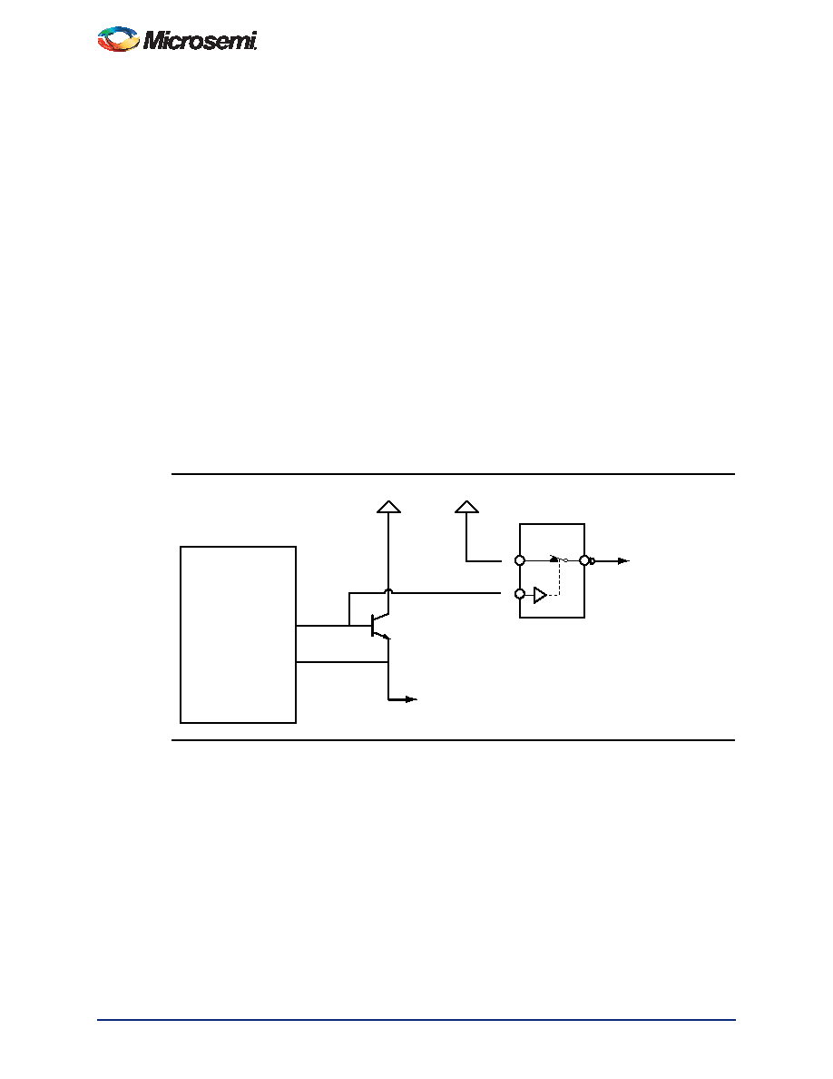
VPUMP and VJTAG can be controlled through an external switch. Microsemi recommends ADG839,
ADG849, or ADG841 as possible switches. Figure 2-28 shows the implementation for controlling
VPUMP. The IN signal of the switch can be connected to PTBASE of the Fusion device. VJTAG can be
controlled in same manner.
Figure 2-28 Implementation to Control VPUMP
PTBASE
PTEM
External
Pass
Transistor
2N2222
3.3 V
1.5 V
VPUMP (or JTAG)
Pin of Fusion
VPUMP (or JTAG) Supply
Fusion
ADG841
S
IN
鐩搁棞PDF璩囨枡 |
PDF鎻忚堪 |
|---|---|
| AFS1500-2FGG676I | IC FPGA 8MB FLASH 1.5M 676-FBGA |
| AFS1500-2FG676I | IC FPGA 8MB FLASH 1.5M 676-FBGA |
| ASC49DREH-S734 | CONN EDGECARD 98POS .100 EYELET |
| M1AFS1500-2FGG676I | IC FPGA 8MB FLASH 1.5M 676-FBGA |
| RSC60DRTF-S13 | CONN EDGECARD 120POS .100 EXTEND |
鐩搁棞浠g悊鍟�/鎶€琛撳弮鏁� |
鍙冩暩鎻忚堪 |
|---|---|
| M1AFS1500-2FGG256 | 鍔熻兘鎻忚堪:IC FPGA 8MB FLASH 1.5M 256-FBGA RoHS:鏄� 椤炲垾:闆嗘垚闆昏矾 (IC) >> 宓屽叆寮� - FPGA锛堢従鍫村彲绶ㄧ▼闁€闄e垪锛� 绯诲垪:Fusion® 鐢㈠搧鍩硅〒妯″:Three Reasons to Use FPGA's in Industrial Designs Cyclone IV FPGA Family Overview 鐗硅壊鐢㈠搧:Cyclone? IV FPGAs 妯欐簴鍖呰:60 绯诲垪:CYCLONE® IV GX LAB/CLB鏁�:9360 閭忚集鍏冧欢/鍠厓鏁�:149760 RAM 浣嶇附瑷�:6635520 杓稿叆/杓稿嚭鏁�:270 闁€鏁�:- 闆绘簮闆诲:1.16 V ~ 1.24 V 瀹夎椤炲瀷:琛ㄩ潰璨艰 宸ヤ綔婧害:0°C ~ 85°C 灏佽/澶栨:484-BGA 渚涙噳鍟嗚ō鍌欏皝瑁�:484-FBGA锛�23x23锛� |
| M1AFS1500-2FGG256ES | 鍒堕€犲晢:ACTEL 鍒堕€犲晢鍏ㄧū:Actel Corporation 鍔熻兘鎻忚堪:Actel Fusion Mixed-Signal FPGAs |
| M1AFS1500-2FGG256I | 鍔熻兘鎻忚堪:IC FPGA 8MB FLASH 1.5M 256-FBGA RoHS:鏄� 椤炲垾:闆嗘垚闆昏矾 (IC) >> 宓屽叆寮� - FPGA锛堢従鍫村彲绶ㄧ▼闁€闄e垪锛� 绯诲垪:Fusion® 妯欐簴鍖呰:1 绯诲垪:ProASICPLUS LAB/CLB鏁�:- 閭忚集鍏冧欢/鍠厓鏁�:- RAM 浣嶇附瑷�:129024 杓稿叆/杓稿嚭鏁�:248 闁€鏁�:600000 闆绘簮闆诲:2.3 V ~ 2.7 V 瀹夎椤炲瀷:琛ㄩ潰璨艰 宸ヤ綔婧害:- 灏佽/澶栨:352-BFCQFP锛屽付鎷夋】 渚涙噳鍟嗚ō鍌欏皝瑁�:352-CQFP锛�75x75锛� |
| M1AFS1500-2FGG256PP | 鍒堕€犲晢:ACTEL 鍒堕€犲晢鍏ㄧū:Actel Corporation 鍔熻兘鎻忚堪:Actel Fusion Mixed-Signal FPGAs |
| M1AFS1500-2FGG484 | 鍔熻兘鎻忚堪:IC FPGA 8MB FLASH 1.5M 484-FBGA RoHS:鏄� 椤炲垾:闆嗘垚闆昏矾 (IC) >> 宓屽叆寮� - FPGA锛堢従鍫村彲绶ㄧ▼闁€闄e垪锛� 绯诲垪:Fusion® 鐢㈠搧鍩硅〒妯″:Three Reasons to Use FPGA's in Industrial Designs Cyclone IV FPGA Family Overview 鐗硅壊鐢㈠搧:Cyclone? IV FPGAs 妯欐簴鍖呰:60 绯诲垪:CYCLONE® IV GX LAB/CLB鏁�:9360 閭忚集鍏冧欢/鍠厓鏁�:149760 RAM 浣嶇附瑷�:6635520 杓稿叆/杓稿嚭鏁�:270 闁€鏁�:- 闆绘簮闆诲:1.16 V ~ 1.24 V 瀹夎椤炲瀷:琛ㄩ潰璨艰 宸ヤ綔婧害:0°C ~ 85°C 灏佽/澶栨:484-BGA 渚涙噳鍟嗚ō鍌欏皝瑁�:484-FBGA锛�23x23锛� |
鐧�(f膩)甯冪穵鎬ラ噰璩硷紝3鍒嗛悩宸﹀彸鎮ㄥ皣寰楀埌鍥炲京銆�
