- 您現(xiàn)在的位置:買(mǎi)賣(mài)IC網(wǎng) > PDF目錄367612 > LU6X14FT Telecommunication IC PDF資料下載
參數(shù)資料
| 型號(hào): | LU6X14FT |
| 英文描述: | Telecommunication IC |
| 中文描述: | 通信集成電路 |
| 文件頁(yè)數(shù): | 6/8頁(yè) |
| 文件大小: | 161K |
| 代理商: | LU6X14FT |

6
Lucent Technologies Inc.
Product Brief
August 2000
1.0—1.25/2.0—2.5/3.125 Gbits/s SERDES
LU6X14FT
Functional Description
(continued)
Reference Clock
The differential clock is distributed to all of the four channels. Each channel has a differential buffer to isolate the
clock from the other channels. The input clock is preferably a differential signal; however, the device can operate
with a single-ended input. The input reference clock directly impacts the transmit data eye, so the clock should have
low jitter. In particular, jitter components in the dc—5 MHz range should be minimized.
Transmitter Section
The block diagram of the transmitter is shown in Figure 2 on page 3. The 8-bit unencoded or 10-bit encoded
parallel input data word is latched into an on-chip register with the externally supplied TBC clock and serialized at
ten times the incoming parallel data rate. When the transmitter is operating in the half rate mode (1.0 Gbits/s—
1.25 Gbits/s), the falling edge of the TBC clock is used to latch the data. When the transmitter is operating in the full
rate mode (2.0 Gbits/s—3.125 Gbits/s), the TBC clock frames the input data so that when TBC is high a bit is
latched by an internal clock and again when TBC is low. The full rate data makes transitions on both edges of the
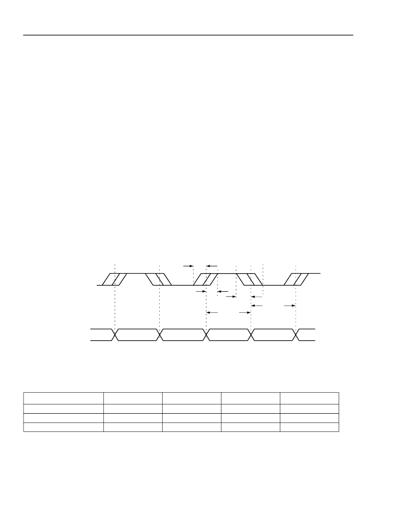
clock as shown in Figure 6 on page 7. Table 2 shows the timing margins.
TBC is the same frequency as REFCLK; however, it is assumed to be of arbitrary phase w.r.t. REFCLK. During a
powerup reset sequence, the phase relationship between REFCLK, TBC, and the PLL generated high-speed clock
is established. The relative phase of the input clocks, TBC and REFCLK, must remain fixed after the powerup
sequence is completed.
A 256-state PRBS generator is included on the chip to enable testability in loopback mode.
0612 (F)
Figure 5. Transmit Timing Diagram
Table 2. Timing Relationship of LDIN and TBC Clock at Full Rate (3.125 Gbits/s)
In the half-rate mode, the incoming data transitions only on the rising edge of the clock, as shown in Figure 6 on
page 7. Table 3 on page 7 shows the timing relationships in this case.
Parameter
t
1
t
2
t
valid
Minimum
—
—
2.5
Typical
—
—
—
Maximum
1.0
0.5
—
Unit
ns
ns
ns
LDIN<7:0>
TBC CLK
t1
t2
t1
tVALID
tVALID
相關(guān)PDF資料 |
PDF描述 |
|---|---|
| LU97 | Telecommunication IC |
| LUC3X01 | LAN Transceiver |
| LUCDA4044 | Phase Frequency Detector |
| LUCDA4044AAPE | HEADER, SMC VERT 4WAY |
| LUCDA4044AAFE | Phase Frequency Detector |
相關(guān)代理商/技術(shù)參數(shù) |
參數(shù)描述 |
|---|---|
| LU70/D | 制造商:OSRAM 功能描述:70W MOGUL BASED GENERAL LIGHTING HIGH PRESSURE SODIUM LAMP, COATED, DAYLIGHT, UN |
| LU70/ECO | 制造商:OSRAM 功能描述:70W MOGUL BASED, ENVIRONMENTALLY FRIENDLIER GENERAL LIGHTING HIGH PRESSURE SODIU |
| LU70/MED | 制造商:OSRAM 功能描述:70W MEDIUM BASED GENERAL LIGHTING HIGH PRESSURE SODIUM LAMP, CLEAR, UNIVERSAL BU |
| LU700Z | 制造商:SEOUL 制造商全稱:Seoul Semiconductor 功能描述:GREEN OVAL LAMP LED |
| LU701 | 制造商:SEOUL 制造商全稱:Seoul Semiconductor 功能描述:RED OVAL LAMP LED |
發(fā)布緊急采購(gòu),3分鐘左右您將得到回復(fù)。