- 您現(xiàn)在的位置:買賣IC網(wǎng) > PDF目錄44995 > LTC3879EUD#TRPBF (LINEAR TECHNOLOGY CORP) SWITCHING CONTROLLER, PQCC16 PDF資料下載
參數(shù)資料
| 型號(hào): | LTC3879EUD#TRPBF |
| 廠商: | LINEAR TECHNOLOGY CORP |
| 元件分類: | 穩(wěn)壓器 |
| 英文描述: | SWITCHING CONTROLLER, PQCC16 |
| 封裝: | 3 X 3 MM, LEAD FREE, PLASTIC, MO-220WEED-4, QFN-16 |
| 文件頁(yè)數(shù): | 11/28頁(yè) |
| 文件大?。?/td> | 302K |
| 代理商: | LTC3879EUD#TRPBF |
第1頁(yè)第2頁(yè)第3頁(yè)第4頁(yè)第5頁(yè)第6頁(yè)第7頁(yè)第8頁(yè)第9頁(yè)第10頁(yè)當(dāng)前第11頁(yè)第12頁(yè)第13頁(yè)第14頁(yè)第15頁(yè)第16頁(yè)第17頁(yè)第18頁(yè)第19頁(yè)第20頁(yè)第21頁(yè)第22頁(yè)第23頁(yè)第24頁(yè)第25頁(yè)第26頁(yè)第27頁(yè)第28頁(yè)

LTC3879
19
3879f
Other losses, which include the COUT ESR loss, bottom
MOSFET reverse recovery loss and inductor core loss
generally account for less than 2% additional loss.
When making adjustments to improve efciency, the input
current is the best indicator of changes in efciency. If you
make a change and the input current decreases, then the
efciency has increased. If there is no change in input
current there is no change in efciency.
Checking Transient Response
The regulator loop response can be checked by look-
ing at the load transient response. Switching regulators
take several cycles to respond to a step in load current.
When a load step occurs, VOUT immediately shifts by an
amount equal to
ΔILOAD (ESR), where ESR is the effective
series resistance of COUT. ΔILOAD also begins to charge
or discharge COUT, generating a feedback error signal
used by the regulator to return VOUT to its steady-state
value. During this recovery time, VOUT can be monitored
for overshoot or ringing that would indicate a stability
problem. The ITH pin external components shown in the
Design Example will provide adequate compensation for
most applications.
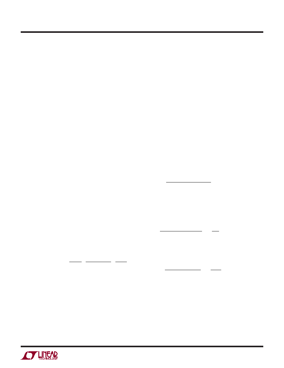
A rough compensation check can be made by calculating
the gain crossover frequency, fGCO. gm(EA) is the error
amplier transconductance, RC is the compensation re-
sistor and feedback divider attenuation is assumed to be
0.6V/VOUT. This equation assumes that no feed-forward
compensation is used on feedback and that COUT sets the
dominant output pole.
fg
R
I
CV
GCO
m EA
C
LIMIT
OUT
=
()
.
.
16
1
2
06
π
As a rule of thumb the gain crossover frequency should be
less than 20% of the switching frequency. For a detailed
explanation of switching control loop theory see Applica-
tion Note 76.
High Switching Frequency Operation
Special care should be taken when operating at switch-
ing frequencies greater than 800kHz. At high switching
frequencies there may be an increased sensitivity to
PCB noise which may result in off-time variation greater
than normal. This off-time instability can be prevented
in several ways. First, carefully follow the recommended
layout techniques. Second, use 2μF or more of X5R or
X7R ceramic input capacitance per Amp of load current.
Third, if necessary, increase the bottom MOSFET ripple
voltage to 30mVP-P or greater. This ripple voltage is equal
to RDS(ON) typical at 25°C IP-P.
Design Example
Figure 10 is a power supply design example with the fol-
lowing specications: VIN = 4.5V to 28V (12V nominal),
VOUT = 1.2V ±5%, IOUT(MAX) = 15A and f = 400kHz. Start
by calculating the timing resistor, RON:
R
V
VkHz
pF
k
ON ==
12
0 7
400
10
429
.
Select the nearest standard resistor value of 432k for a
nominal operating frequency of 396kHz. Set the inductor
value to give 35% ripple current at maximum VIN using
the adjusted operating frequency:
L
V
kHz
A
μH
=
=
12
396
0 35 15
1
12
28
055
.
–
.
Select 0.56μH which is the nearest value.
The resulting maximum ripple current is:
ΔI
V
kHz
μH
V
A
L =
=
12
396
0 56
1
12
28
51
.
–
.
Choose the synchronous bottom MOSFET switch and
calculate the VRNG current limit set-point. To calculate
VRNG and VDS, the ρτ term normalization factor (unity
APPLICATIONS INFORMATION
相關(guān)PDF資料 |
PDF描述 |
|---|---|
| LTC3879IUD#PBF | SWITCHING CONTROLLER, PQCC16 |
| LTC3880IUJ-1#TRPBF | 0.1 A DUAL SWITCHING CONTROLLER, 1000 kHz SWITCHING FREQ-MAX, PQCC40 |
| LTC3880IUJ#PBF | 0.1 A DUAL SWITCHING CONTROLLER, 1000 kHz SWITCHING FREQ-MAX, PQCC40 |
| LTC3880EUJ-1#TRPBF | 0.1 A DUAL SWITCHING CONTROLLER, 1000 kHz SWITCHING FREQ-MAX, PQCC40 |
| LTC3880EUJ-1#PBF | 0.1 A DUAL SWITCHING CONTROLLER, 1000 kHz SWITCHING FREQ-MAX, PQCC40 |
相關(guān)代理商/技術(shù)參數(shù) |
參數(shù)描述 |
|---|---|
| LTC3879IMSE#PBF | 功能描述:IC REG CTRLR BUCK PWM CM 16-MSOP RoHS:是 類別:集成電路 (IC) >> PMIC - 穩(wěn)壓器 - DC DC 切換控制器 系列:- 標(biāo)準(zhǔn)包裝:2,500 系列:- PWM 型:電流模式 輸出數(shù):1 頻率 - 最大:500kHz 占空比:96% 電源電壓:4 V ~ 36 V 降壓:無(wú) 升壓:是 回掃:無(wú) 反相:無(wú) 倍增器:無(wú) 除法器:無(wú) Cuk:無(wú) 隔離:無(wú) 工作溫度:-40°C ~ 125°C 封裝/外殼:24-WQFN 裸露焊盤 包裝:帶卷 (TR) |
| LTC3879IMSE#TRPBF | 功能描述:IC REG CTRLR BUCK PWM CM 16-MSOP RoHS:是 類別:集成電路 (IC) >> PMIC - 穩(wěn)壓器 - DC DC 切換控制器 系列:- 標(biāo)準(zhǔn)包裝:2,500 系列:- PWM 型:電流模式 輸出數(shù):1 頻率 - 最大:500kHz 占空比:96% 電源電壓:4 V ~ 36 V 降壓:無(wú) 升壓:是 回掃:無(wú) 反相:無(wú) 倍增器:無(wú) 除法器:無(wú) Cuk:無(wú) 隔離:無(wú) 工作溫度:-40°C ~ 125°C 封裝/外殼:24-WQFN 裸露焊盤 包裝:帶卷 (TR) |
| LTC3879IUD#PBF | 功能描述:IC REG CTRLR BUCK PWM CM 16-QFN RoHS:是 類別:集成電路 (IC) >> PMIC - 穩(wěn)壓器 - DC DC 切換控制器 系列:- 標(biāo)準(zhǔn)包裝:2,500 系列:- PWM 型:電流模式 輸出數(shù):1 頻率 - 最大:500kHz 占空比:96% 電源電壓:4 V ~ 36 V 降壓:無(wú) 升壓:是 回掃:無(wú) 反相:無(wú) 倍增器:無(wú) 除法器:無(wú) Cuk:無(wú) 隔離:無(wú) 工作溫度:-40°C ~ 125°C 封裝/外殼:24-WQFN 裸露焊盤 包裝:帶卷 (TR) |
| LTC3879IUD#TRPBF | 功能描述:IC REG CTRLR BUCK PWM CM 16-QFN RoHS:是 類別:集成電路 (IC) >> PMIC - 穩(wěn)壓器 - DC DC 切換控制器 系列:- 標(biāo)準(zhǔn)包裝:2,500 系列:- PWM 型:電流模式 輸出數(shù):1 頻率 - 最大:500kHz 占空比:96% 電源電壓:4 V ~ 36 V 降壓:無(wú) 升壓:是 回掃:無(wú) 反相:無(wú) 倍增器:無(wú) 除法器:無(wú) Cuk:無(wú) 隔離:無(wú) 工作溫度:-40°C ~ 125°C 封裝/外殼:24-WQFN 裸露焊盤 包裝:帶卷 (TR) |
| LTC3880EUJ#PBF | 功能描述:IC REG CTRLR BUCK PWM CM 40-QFN RoHS:是 類別:集成電路 (IC) >> PMIC - 穩(wěn)壓器 - DC DC 切換控制器 系列:PolyPhase® 特色產(chǎn)品:LM3753/54 Scalable 2-Phase Synchronous Buck Controllers 標(biāo)準(zhǔn)包裝:1 系列:PowerWise® PWM 型:電壓模式 輸出數(shù):1 頻率 - 最大:1MHz 占空比:81% 電源電壓:4.5 V ~ 18 V 降壓:是 升壓:無(wú) 回掃:無(wú) 反相:無(wú) 倍增器:無(wú) 除法器:無(wú) Cuk:無(wú) 隔離:無(wú) 工作溫度:-5°C ~ 125°C 封裝/外殼:32-WFQFN 裸露焊盤 包裝:Digi-Reel® 產(chǎn)品目錄頁(yè)面:1303 (CN2011-ZH PDF) 其它名稱:LM3754SQDKR |
發(fā)布緊急采購(gòu),3分鐘左右您將得到回復(fù)。