- 您現(xiàn)在的位置:買賣IC網(wǎng) > PDF目錄44968 > LSM2-T/16-D12N-C (CD TECHNOLOGIES INC) 1-OUTPUT 52.8 W DC-DC REG PWR SUPPLY MODULE PDF資料下載
參數(shù)資料
| 型號: | LSM2-T/16-D12N-C |
| 廠商: | CD TECHNOLOGIES INC |
| 元件分類: | 電源模塊 |
| 英文描述: | 1-OUTPUT 52.8 W DC-DC REG PWR SUPPLY MODULE |
| 封裝: | ROHS COMPLIANT PACKAGE-8 |
| 文件頁數(shù): | 2/17頁 |
| 文件大?。?/td> | 1504K |
| 代理商: | LSM2-T/16-D12N-C |
MDC_LSM2 Series.B01 Page 10 of 17
Technical enquiries email: sales@murata-ps.com, tel: +1 508 339 3000
www.murata-ps.com
LSM2 Series
Single Putput, Non-Isolated
Selectable-Output POL DC/DC Converters
Tape & Reel Surface Mount Package
MPS’s LSM2 series DC/DC converters are the only higher-current (16A) SMT
DC/DC's that can be automatically “pick-and-placed” using standard vacuum-
pickup equipment (nozzle size and style, vacuum pressure and placement
speed may need to be optimized for automated pick and place) and subse-
quently reflowed using high-temperature, lead-free solder.
Virtually all SMT DC/DCs today are unprotected "open-frame" devices as-
sembled by their vendors with high-temperature solder (usually Sn96.5/Ag3.5
with a melting point +221°C) so that you may attach them to your board using
low-temperature solder (usually Sn63/Pb37 with a melting point of +183°C).
Conceptually straightforward, this "stepped" solder approach has its limita-
tions, and it is clearly out of step with an industry trending toward the broad
use of lead-free solders. Are you to experiment and develop reflow profiles
from other vendors that ensure the components on those DC/DC never exceed
215-216°C? If those components get too hot, "double-reflow" could compro-
mise the reliability of their solder joints. Virtually all these devices demand you
"cool down" the Sn63 profile you are likely using today.
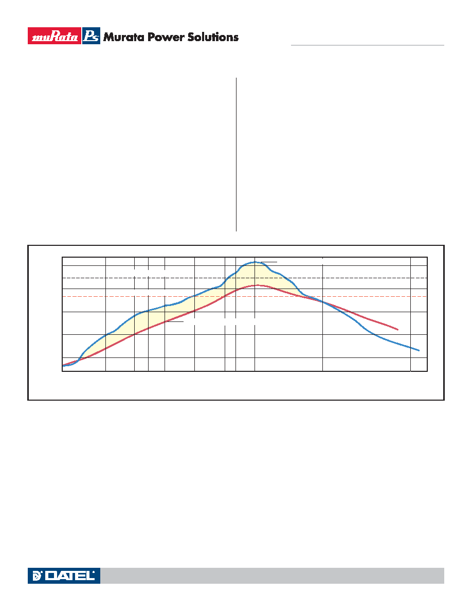
Figure 6. Reflow Solder Profile
MPS is not exempted from the Laws of Physics, and we do not have
magic solders no one else has. Nevertheless, we have a simple and practical,
straightforward approach that works. We assemble our LSM2 SMT DC/DC's
using a high-temperature (+216°C), lead-free alloy (Sn96.2%, Ag2.5%, Cu0.8%,
Sb0.5%). The LSM2 design ensures co-planarity to within 0.004 inches
(1001m) of the unit's tin-plated (150 micro-inches) copper leads. See Me-
chanical Data for additional information.
The disposable heat shield (patent pending), which has a cutaway expos-
ing the package leads, provides thermal insulation to internal components
during reflow and its smooth surface ideally doubles as the vacuum pick-up
location also. The insulation properties of the heat shield are so effective
that temperature differentials as high as 50°C develop inside-to-outside the
shield. Oven temperature profiles with peaks of 250-260°C and dwell times
exceeding 2 minutes above 221°C (the melting point of Sn96.5/Ag3.5) are
easily achieved.
HEAT SHIELD OUTSIDE TEMPERATURE
Sn96.5/Ag3.5 Melting Point
Sn63/Pb37 Melting Point
250
200
150
100
50
0
50
100
150
200
250
300
350
400
221
183
PCB TEMPERATURE INSIDE THE HEAT SHIELD
Te
mperature
(
C)
Time (Seconds)
相關(guān)PDF資料 |
PDF描述 |
|---|---|
| LSM2-T/6-W3NG-C | 1-OUTPUT 19.8 W DC-DC REG PWR SUPPLY MODULE |
| LSM2-T/16-W3NG-C | 1-OUTPUT 52.8 W DC-DC REG PWR SUPPLY MODULE |
| LSM2-T/10-W3-C | 1-OUTPUT 33 W DC-DC REG PWR SUPPLY MODULE |
| LSM2-T/6-W3-C | 1-OUTPUT 19.8 W DC-DC REG PWR SUPPLY MODULE |
| LSM2-T/16-D12G-C | 1-OUTPUT 52.8 W DC-DC REG PWR SUPPLY MODULE |
相關(guān)代理商/技術(shù)參數(shù) |
參數(shù)描述 |
|---|---|
| LSM2-T30-D12 | 制造商:MURATA 制造商全稱:Murata Manufacturing Co., Ltd. 功能描述:DOSA-SMT, 30A POL DC/DC Converters |
| LSM2-T-30-D12-C | 制造商:MURATA 制造商全稱:Murata Manufacturing Co., Ltd. 功能描述:DOSA-SMT, 30A POL DC/DC Converters |
| LSM2-T30-D12-C | 制造商:MURATA 制造商全稱:Murata Manufacturing Co., Ltd. 功能描述:DOSA-SMT, 30A POL DC/DC Converters |
| LSM2-T-30-D12R-C | 制造商:MURATA 制造商全稱:Murata Manufacturing Co., Ltd. 功能描述:DOSA-SMT, 30A POL DC/DC Converters |
| LSM2-T30-D12R-C | 制造商:MURATA 制造商全稱:Murata Manufacturing Co., Ltd. 功能描述:DOSA-SMT, 30A POL DC/DC Converters |
發(fā)布緊急采購,3分鐘左右您將得到回復(fù)。