- 您現(xiàn)在的位置:買賣IC網(wǎng) > PDF目錄44766 > LS1301-7RD1TB1 1-OUTPUT AC-DC REG PWR SUPPLY MODULE PDF資料下載
參數(shù)資料
| 型號: | LS1301-7RD1TB1 |
| 元件分類: | 電源模塊 |
| 英文描述: | 1-OUTPUT AC-DC REG PWR SUPPLY MODULE |
| 封裝: | METAL, CASE S02, MODULE |
| 文件頁數(shù): | 17/23頁 |
| 文件大?。?/td> | 526K |
| 代理商: | LS1301-7RD1TB1 |
Rugged Environment
AC-DC Converters <100 W
S-Family
Edition 2/96 - Melcher AG
10 - 25
MELCHER
The Power Partners.
10.1
Installation
Installation must strictly follow the national safety regula-
tions. Pin 24 has to be connected to earth. A second fuse
should be installed in the wiring to pins 26/28 if:
– Local requirements demand an individual fuse in each
source line
– Neutral to protective earth impedance is high or unde-
fined
– Phase and neutral of the mains are not defined.
In applications where the inhibit function is not used, the
inhibit pin should be connected to the S– pin (S 1000) or
the Vo1– pin (S 2000) to enable the outputs.
Important Advice
Electric strength tests should not be repeated in the field.
Improper test methods, for example overshooting or os-
cillating test voltages, voltage slopes exceeding 1 kV/
s,
internal Y-capacitors not carefully discharged, etc. can
cause severe damage to switching devices and ICs.
Melcher will not honour any guarantee/warranty claims
resulting from high voltage field tests.
Table 2: H15 Connector pin allocation
Pin
Connector type H 15
No.
LS 1000
LS 2000
4
Vo1+
Output 1
Vo2+
Output 2
6
Vo1+
Vo2+
8
Vo1–
Output 1
Vo2–
Output 2
10
Vo1–
Vo2–
12
S+
Sense
Vo1+
Output 1
14
S–
Sense
Vo1–
Output 1
16
R 1
Control of
U o1
R 1
Control of
U o1
18
Inhibit
i
Inhibit
20
D 3
Save data
D
Save data
V 3
ACFAIL
22
T
Current sharing T
Current sharing
24 2
Protective earth
26
N
Neutral
N
Neutral
28
N
30
P
Phase
P
Phase
32
P
1 Feature R excludes option P and, vice versa
2 Leading pin (pregrounding)
3 Option D excludes option V and vice versa.
Degree of Protection
Condition: Female connector fitted to the unit.
IP 30: All units except those with options P, D or V with
potentiometer adjustment.
IP 20: All units fitted with options which include poten-
tiometer setting.
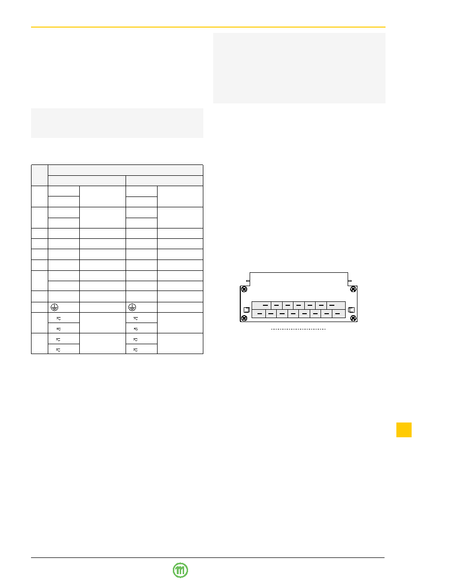
4
32
Type H15
Fig. 1
View of male connector
相關PDF資料 |
PDF描述 |
|---|---|
| LS1301-7RD8TB1 | 1-OUTPUT AC-DC REG PWR SUPPLY MODULE |
| LS2320-7RD3TB1 | 2-OUTPUT AC-DC REG PWR SUPPLY MODULE |
| LS2540-9RDDTB1 | 2-OUTPUT AC-DC REG PWR SUPPLY MODULE |
| LS1601-7RDDTB1 | 1-OUTPUT AC-DC REG PWR SUPPLY MODULE |
| LS1601-9RD3TB1 | 1-OUTPUT AC-DC REG PWR SUPPLY MODULE |
相關代理商/技術參數(shù) |
參數(shù)描述 |
|---|---|
| LS1301-9ER | 制造商:Power-One 功能描述:ACDC - Bulk |
| LS1301-9R | 制造商:Power-One 功能描述:ACDC - Bulk |
| LS130A_PDIP | 制造商:MICROSS 制造商全稱:MICROSS 功能描述:MONOLITHIC DUAL NPN TRANSISTOR |
| LS130A_SOIC | 制造商:MICROSS 制造商全稱:MICROSS 功能描述:MONOLITHIC DUAL NPN TRANSISTOR |
| LS130A_SOT-23 | 制造商:MICROSS 制造商全稱:MICROSS 功能描述:MONOLITHIC DUAL NPN TRANSISTOR |
發(fā)布緊急采購,3分鐘左右您將得到回復。