- 您現(xiàn)在的位置:買賣IC網(wǎng) > PDF目錄385498 > LQA48B (National Semiconductor Corporation) Cellular Phone Power Management Unit PDF資料下載
參數(shù)資料
| 型號(hào): | LQA48B |
| 廠商: | National Semiconductor Corporation |
| 英文描述: | Cellular Phone Power Management Unit |
| 中文描述: | 蜂窩電話電源管理單元 |
| 文件頁數(shù): | 14/32頁 |
| 文件大小: | 761K |
| 代理商: | LQA48B |
第1頁第2頁第3頁第4頁第5頁第6頁第7頁第8頁第9頁第10頁第11頁第12頁第13頁當(dāng)前第14頁第15頁第16頁第17頁第18頁第19頁第20頁第21頁第22頁第23頁第24頁第25頁第26頁第27頁第28頁第29頁第30頁第31頁第32頁
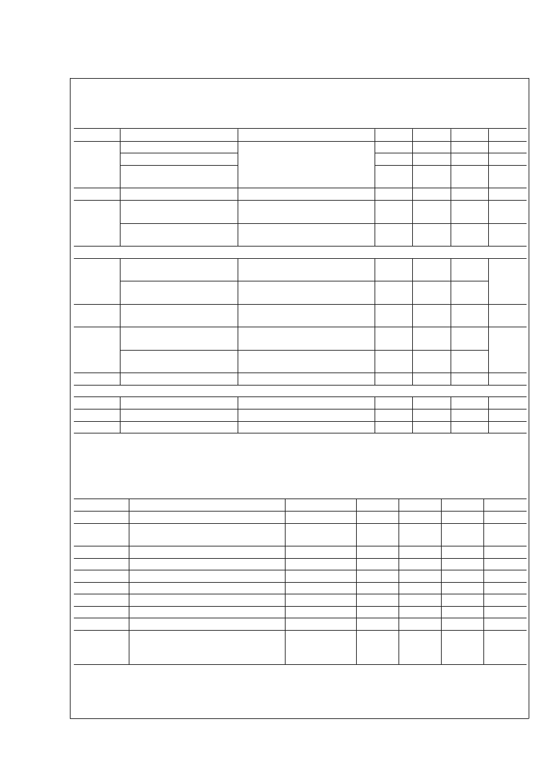
Main Battery Charger Electrical Characteristics
(Continued)
Unless otherwise noted, V
= 5V, V
= 4V. Typical values and limits appearing in normal type apply for T
= 25C.
Limits appearing in
boldface
type apply over the entire junction temperature range for operation, 40 to +125C. (Notes 2, 9,
8, 12)
Symbol
I
CHG
Parameter
Condition
Min
10
478
Typ
±
5
Max
+10
937
Units
%
mA
Fast Charge Current Accuracy
Fast Charge Current Range
Programmable Charging
Current Step
Pre-Charge Current
Internal Current Sense
Resistance
Internal Current Sense Resistor
Load Current
CHARGING PERFORMANCE
V
BATT
Battery Regulation Voltage
(CV Mode, for 4.1V Cell)
Battery Regulation Voltage
CV mode, for 4.2V Cell)
V
CHG-Q
Full Charge Qualification
Threshold
V
BAT-RST
Restart Threshold Voltage
(For 4.1V Cell)
Restart Threshold Voltage
(For 4.2 Cell)
t
EOC
Time to EOC State
A/D CONVERTER PERFORMANCE
Resolution
INL
Relative Accuracy
DNL
Differential Nonlinearity
Note:
While charging a Li-Ion battery with this charger is possible in cold temperatures (generally below 5C–0C) is possible with the LP3941A, charging a battery
outside its manufacturer recommended temperature limits is strongly discouraged.
I
CHG
= 700 mA
43
mA
I
PRE
CHG
R
SENSE
V
BATT
= 2V
28
42
59
mA
120
m
1.2
A
T
A
40C to +85C
4.015
4.1
4.19
T
A
40C to +85C
4.115
4.2
4.289
V
BATT
Rising, Transition from
Pre-Charge to Full Current
V
BATT
Falling, Transition from EOC,
to Pre-Qual State
V
BATT
Falling, Transition from EOC,
to Pre-Qual State
40C to +85C (Note 10)
2.8
3.0
3.2
V
3.9
V
4.0
4.80
5.625
6.55
Hrs
8
Bits
LSB
LSB
1
1
+1
+1
No Missing Code
I
2
C Compatible Interface Electrical Characteristics
Unless otherwise noted, V
BATT
= +2.5V to 5.5V. Typical values and limits appearing in normal type apply for T
J
= 25C. Limits
appearing in
boldface
type apply over the entire junction temperature range for operation, 40 to +125C. (Notes 2, 8, 9)
Symbol
F
CLK
t
BF
Parameter
Condition
Min
Typ
Max
400
Units
kHz
Clock Frequency
Bus-Free Time between START and
STOP
Hold Time Repeated START Condition
CLK Low Period
CLK High Period
Set-Up Time Repeated START Condition
Data Hold Time
Data Set-Up Time
Set-Up Time for STOP Condition
Maximum Pulse Width of Spikes that must
be suppressed by the input filter of both
DATA & CLK signals.
(Note 10)
1.3
μs
t
HOLD
t
CLK-LP
t
CLK-HP
t
SU
t
DATA-HOLD
t
DATA-SU
t
SU
t
TRANS
(Note 10)
(Note 10)
(Note 10)
(Note 10)
(Note 10)
(Note 10)
(Note 10)
(Note 10)
0.6
1.3
0.6
0.6
0
100
0.6
μs
μs
μs
μs
μs
ns
μs
50
ns
Note 1:
Absolute Maximum Ratings are limits beyond which damage to the device may occur. Operating Ratings are conditions under which operation of the device
is guaranteed. Operating Ratings do not imply guaranteed performance limits. For guaranteed performance limits and associated test conditions, see the Electrical
Characteristics tables.
Note 2:
All voltages are with respect to the potential at the GND pin.
Note 3:
The amount of Absolute Maximum power dissipation allowed for the device depends on the ambient temperature and can be calculated using the formula
L
www.national.com
14
相關(guān)PDF資料 |
PDF描述 |
|---|---|
| LQB08A | Single-Ended Input Motor Driver |
| LS248 | BCD TO 7-SEGMENT DECODER |
| LT-5 | Axial Lead and Cartridge Fuses |
| LT1003 | 5V,5A,Voltage Regulator(5V,5A輸出,線性穩(wěn)壓器) |
| LT1004 | Micropower Voltage Reference(微功耗電壓基準(zhǔn)) |
相關(guān)代理商/技術(shù)參數(shù) |
參數(shù)描述 |
|---|---|
| LQA60A300C | 功能描述:整流器 Q-Series 300V 30A Dual Ultra-Low Qrr RoHS:否 制造商:Vishay Semiconductors 產(chǎn)品:Standard Recovery Rectifiers 配置: 反向電壓:100 V 正向電壓下降: 恢復(fù)時(shí)間:1.2 us 正向連續(xù)電流:2 A 最大浪涌電流:35 A 反向電流 IR:5 uA 安裝風(fēng)格:SMD/SMT 封裝 / 箱體:DO-221AC 封裝:Reel |
| LQB08A | 制造商:NSC 制造商全稱:National Semiconductor 功能描述:Single-Ended Input Motor Driver |
| LQB10A15NJ00T1M0-501 | 制造商:Murata Manufacturing Co Ltd 功能描述: |
| LQB15MN1N0B02B | 制造商:MURATA 制造商全稱:Murata Manufacturing Co., Ltd. 功能描述:Chip Inductor (Chip Coil) for High Frequency Film Type LQP15M Series |
| LQB15MN1N0W02B | 制造商:MURATA 制造商全稱:Murata Manufacturing Co., Ltd. 功能描述:Chip Inductor (Chip Coil) for High Frequency Film Type LQP15M Series |
發(fā)布緊急采購,3分鐘左右您將得到回復(fù)。