- 您現在的位置:買賣IC網 > PDF目錄384606 > LP55281RL (NATIONAL SEMICONDUCTOR CORP) Quad RGB Driver PDF資料下載
參數資料
| 型號: | LP55281RL |
| 廠商: | NATIONAL SEMICONDUCTOR CORP |
| 元件分類: | 顯示驅動器 |
| 英文描述: | Quad RGB Driver |
| 中文描述: | LED DISPLAY DRIVER, PBGA36 |
| 封裝: | 3 X 3 MM, 0.65 MM HEIGHT, 0.50 MM PITCH, MICRO SMD-36 |
| 文件頁數: | 17/28頁 |
| 文件大小: | 1313K |
| 代理商: | LP55281RL |
第1頁第2頁第3頁第4頁第5頁第6頁第7頁第8頁第9頁第10頁第11頁第12頁第13頁第14頁第15頁第16頁當前第17頁第18頁第19頁第20頁第21頁第22頁第23頁第24頁第25頁第26頁第27頁第28頁
LED TEST PROCEDURE
An example of LED test sequence is presented here. Note, that user can use incremental write sequence on I
2
C. The test sequence
consists of the basic setup and measurement phases for all RGB LEDs and Boost voltage.
Basic setup phase for the device:
1.
2.
3.
4.
5.
6.
7.
8.
9.
10. Set the preferred value for BLUE3 (write 3Fh, 7Fh, BFh or FFh to register 08h)
11. Set the preferred value for RED4 (write 3Fh, 7Fh, BFh or FFh to register 09h)
12. Set the preferred value for GREEN4 (write 3Fh, 7Fh, BFh or FFh to register 0Ah)
13. Set the preferred value for BLUE4 (write 3Fh, 7Fh, BFh or FFh to register 0Bh)
14. Set the preferred value for ALED (write 01h - FFh to register 0Ch)
15. Dummy write: 00h to register 0Dh (Only if the incremental write sequence is used)
16. Dummy write: 00h to register 0Eh (Only if the incremental write sequence is used)
17. Set preferred boost voltage (write 00h - FFh to register 0Fh)
18. Set preferred boost frequency (write 00h - 07h to register 10h, PWM frequency can be anything)
19. Enable boost and RGB drivers (write CFh to register 11h)
20. Wait 20 ms for the device and boost startup
Give reset to LP55281 (by power on, NRST pin or write any data to register 60h)
Set the preferred value for RED1 (write 3Fh, 7Fh, BFh or FFh to register 00h)
Set the preferred value for GREEN1 (write 3Fh, 7Fh, BFh or FFh to register 01h)
Set the preferred value for BLUE1 (write 3Fh, 7Fh, BFh or FFh to register 02h)
Set the preferred value for RED2 (write 3Fh, 7Fh, BFh or FFh to register 03h)
Set the preferred value for GREEN2 (write 3Fh, 7Fh, BFh or FFh to register 04h)
Set the preferred value for BLUE2 (write 3Fh, 7Fh, BFh or FFh to register 05h)
Set the preferred value for RED3 (write 3Fh, 7Fh, BFh or FFh to register 06h)
Set the preferred value for GREEN3 (write 3Fh, 7Fh, BFh or FFh to register 07h)
Measurement phase:
1.
2.
3.
4.
5.
Enable LED test and select output (write 1xh to register 12h)
Wait for 128 μs
Read ADC output (read register 13h)
Go to step 1 of measurement phase and define next output to be measured as many times as needed
Disable LED test (write 00h to register 12h) or give reset to the device (see step 1 in basic setup phase)
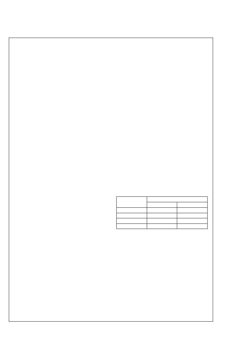
LED TEST TIME ESTIMATION
Assuming the maximum clock frequencies used in SPI or I
2
C
compatible interfaces, the following table predicts the overall
test sequence time for the test procedure shown above. This
estimation gives the shortest time possible. Incremental write
is assumed with I
2
C. Reset and LED test disable are not in-
cluded.
Test Phase
Time (ms)
I
2
C
SPI
Setup
0.528
20
4.137
24.7
0.024
20
1.831
21.9
Boost startup
14 measurements
Total Time
17
www.national.com
L
相關PDF資料 |
PDF描述 |
|---|---|
| LP55281RLX | Quad RGB Driver |
| LP55281TL | Quad RGB Driver |
| LP55281TLX | Quad RGB Driver |
| LP5551 | PowerWise⑩ Technology Compliant Energy Management Unit |
| LP5551SQ | PowerWise⑩ Technology Compliant Energy Management Unit |
相關代理商/技術參數 |
參數描述 |
|---|---|
| LP55281RL/NOPB | 功能描述:LED照明驅動器 RoHS:否 制造商:STMicroelectronics 輸入電壓:11.5 V to 23 V 工作頻率: 最大電源電流:1.7 mA 輸出電流: 最大工作溫度: 安裝風格:SMD/SMT 封裝 / 箱體:SO-16N |
| LP55281RLEV | 功能描述:LED 照明開發(fā)工具 LP55281RLEV EVAL BOARD RoHS:否 制造商:Fairchild Semiconductor 產品:Evaluation Kits 用于:FL7732 核心: 電源電壓:120V 系列: 封裝: |
| LP55281RLEV/NOPB | 制造商:Texas Instruments 功能描述:QUAD RGB DRIVER - Boxed Product (Development Kits) 制造商:Texas Instruments 功能描述:BOARD EVAL FOR LP5528 RGB DRIVER 制造商:Texas Instruments 功能描述:Quad RGB Drvr fr the PowerWise Family |
| LP55281RLX | 制造商:NSC 制造商全稱:National Semiconductor 功能描述:Quad RGB Driver |
| LP55281RLX/NOPB | 功能描述:LED照明驅動器 RoHS:否 制造商:STMicroelectronics 輸入電壓:11.5 V to 23 V 工作頻率: 最大電源電流:1.7 mA 輸出電流: 最大工作溫度: 安裝風格:SMD/SMT 封裝 / 箱體:SO-16N |
發(fā)布緊急采購,3分鐘左右您將得到回復。