- 您現(xiàn)在的位置:買賣IC網(wǎng) > PDF目錄384606 > LP5520TL (NATIONAL SEMICONDUCTOR CORP) RGB Backlight LED Driver PDF資料下載
參數(shù)資料
| 型號(hào): | LP5520TL |
| 廠商: | NATIONAL SEMICONDUCTOR CORP |
| 元件分類: | 顯示驅(qū)動(dòng)器 |
| 英文描述: | RGB Backlight LED Driver |
| 中文描述: | LED DISPLAY DRIVER, PBGA25 |
| 封裝: | 2.77 X 2.59 MM, 0.60 MM HEIGHT, SMD-25 |
| 文件頁(yè)數(shù): | 19/34頁(yè) |
| 文件大?。?/td> | 790K |
| 代理商: | LP5520TL |
第1頁(yè)第2頁(yè)第3頁(yè)第4頁(yè)第5頁(yè)第6頁(yè)第7頁(yè)第8頁(yè)第9頁(yè)第10頁(yè)第11頁(yè)第12頁(yè)第13頁(yè)第14頁(yè)第15頁(yè)第16頁(yè)第17頁(yè)第18頁(yè)當(dāng)前第19頁(yè)第20頁(yè)第21頁(yè)第22頁(yè)第23頁(yè)第24頁(yè)第25頁(yè)第26頁(yè)第27頁(yè)第28頁(yè)第29頁(yè)第30頁(yè)第31頁(yè)第32頁(yè)第33頁(yè)第34頁(yè)
Magnetic High Voltage Boost DC/DC Converter
The LP5520 Boost DC/DC Converter generates a 5 to 20V
supply voltage for the LEDs from single Li-Ion battery (2.9 to
4.5V). The output voltage is controlled with four bits in 18
steps. In adaptive mode the output voltage is automatically
adjusted so that the LED drivers have enough voltage for
proper operation. The converter is a magnetic switching PWM
mode DC/DC converter with a current limit. Switching fre-
quency is 1 MHz. Boost converter options are controlled with
few bits of
Control
(06H) register.
<en_autoload> (bit 3)
0
1
0
1
0
1
0
1
Internal boost converter loader off
Internal boost converter loader on
Manual boost output adjustment
Adaptive boost output adjustment
Boost converter standby mode
Boost converter active mode
LP5520 standby mode
LP5520 active mode
<vout_auto> (bit 2)
<en_boost> (bit 1)
<nstby> (bit 0)
The LP5520 Boost Converter uses pulse-skipping elimination
to stabilize the noise spectrum. Even with light load or no load
a minimum length current pulse is fed to the inductor. An ac-
tive load is used to remove the excess charge from the output
capacitor at very light loads. Active load can be disabled with
the
<en_autoload>
bit. Disabling active load will increase
slightly the efficiency at light loads, but the downside is that
pulse skipping will occur. The Boost Converter should be
stopped when there is no load to minimize the current con-
sumption.
The topology of the magnetic boost converter is called CPM
control, current programmed mode, where the inductor cur-
rent is measured and controlled with the feedback. The user
can program the output voltage of the boost converter. The
output voltage control changes the resistor divider in the feed-
back loop.
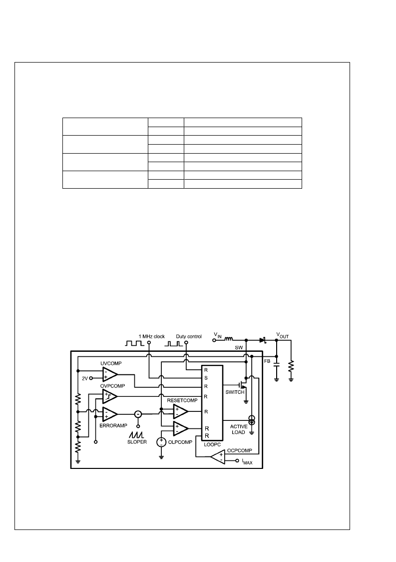
The following figure shows the boost topology with the pro-
tection circuitry. Four different protection schemes are imple-
mented:
1.
Over voltage protection, limits the maximum output
voltage
—
Keeps the output below breakdown voltage.
—
Prevents boost operation if battery voltage is much
higher than desired output.
Over current protection, limits the maximum inductor
current
—
Voltage over switching NMOS is monitored; too high
voltages turn the switch off.
Feedback break protection. Prevents uncontrolled
operation if FB pin gets disconnected.
Duty cycle limiting, done with digital control.
2.
3.
4.
20186120
Boost Converter Topology
19
www.national.com
L
相關(guān)PDF資料 |
PDF描述 |
|---|---|
| LP5520TLX | RGB Backlight LED Driver |
| LP5521 | Programmable Three Channel LED Driver |
| LP5521TM | Programmable Three Channel LED Driver |
| LP5521TMX | Programmable Three Channel LED Driver |
| LP5521YQ | Programmable Three Channel LED Driver |
相關(guān)代理商/技術(shù)參數(shù) |
參數(shù)描述 |
|---|---|
| LP5520TL/NOPB | 功能描述:LED照明驅(qū)動(dòng)器 RoHS:否 制造商:STMicroelectronics 輸入電壓:11.5 V to 23 V 工作頻率: 最大電源電流:1.7 mA 輸出電流: 最大工作溫度: 安裝風(fēng)格:SMD/SMT 封裝 / 箱體:SO-16N |
| LP5520TLX | 制造商:NSC 制造商全稱:National Semiconductor 功能描述:RGB Backlight LED Driver |
| LP5520TLX/NOPB | 功能描述:LED照明驅(qū)動(dòng)器 RoHS:否 制造商:STMicroelectronics 輸入電壓:11.5 V to 23 V 工作頻率: 最大電源電流:1.7 mA 輸出電流: 最大工作溫度: 安裝風(fēng)格:SMD/SMT 封裝 / 箱體:SO-16N |
| LP5521 | 制造商:NSC 制造商全稱:National Semiconductor 功能描述:Programmable Three Channel LED Driver |
| LP5521TM | 制造商:NSC 制造商全稱:National Semiconductor 功能描述:Programmable Three Channel LED Driver |
發(fā)布緊急采購(gòu),3分鐘左右您將得到回復(fù)。