- 您現(xiàn)在的位置:買賣IC網(wǎng) > PDF目錄296315 > LM4549BVHX/NOPB (NATIONAL SEMICONDUCTOR CORP) LM4549B AC '97 Rev 2.1 Multi-Channel Audio Codec with Sample Rate Conversion and National 3D Sound; Package: LQFP; No of Pins: 48; Qty per Container: 1000/Reel PDF資料下載
參數(shù)資料
| 型號: | LM4549BVHX/NOPB |
| 廠商: | NATIONAL SEMICONDUCTOR CORP |
| 元件分類: | 消費家電 |
| 英文描述: | LM4549B AC '97 Rev 2.1 Multi-Channel Audio Codec with Sample Rate Conversion and National 3D Sound; Package: LQFP; No of Pins: 48; Qty per Container: 1000/Reel |
| 中文描述: | SPECIALTY CONSUMER CIRCUIT, PQFP48 |
| 封裝: | 7 X 7 MM, 1.40 MM HEIGHT, LQFP-48 |
| 文件頁數(shù): | 16/28頁 |
| 文件大?。?/td> | 927K |
| 代理商: | LM4549BVHX/NOPB |
第1頁第2頁第3頁第4頁第5頁第6頁第7頁第8頁第9頁第10頁第11頁第12頁第13頁第14頁第15頁當前第16頁第17頁第18頁第19頁第20頁第21頁第22頁第23頁第24頁第25頁第26頁第27頁第28頁
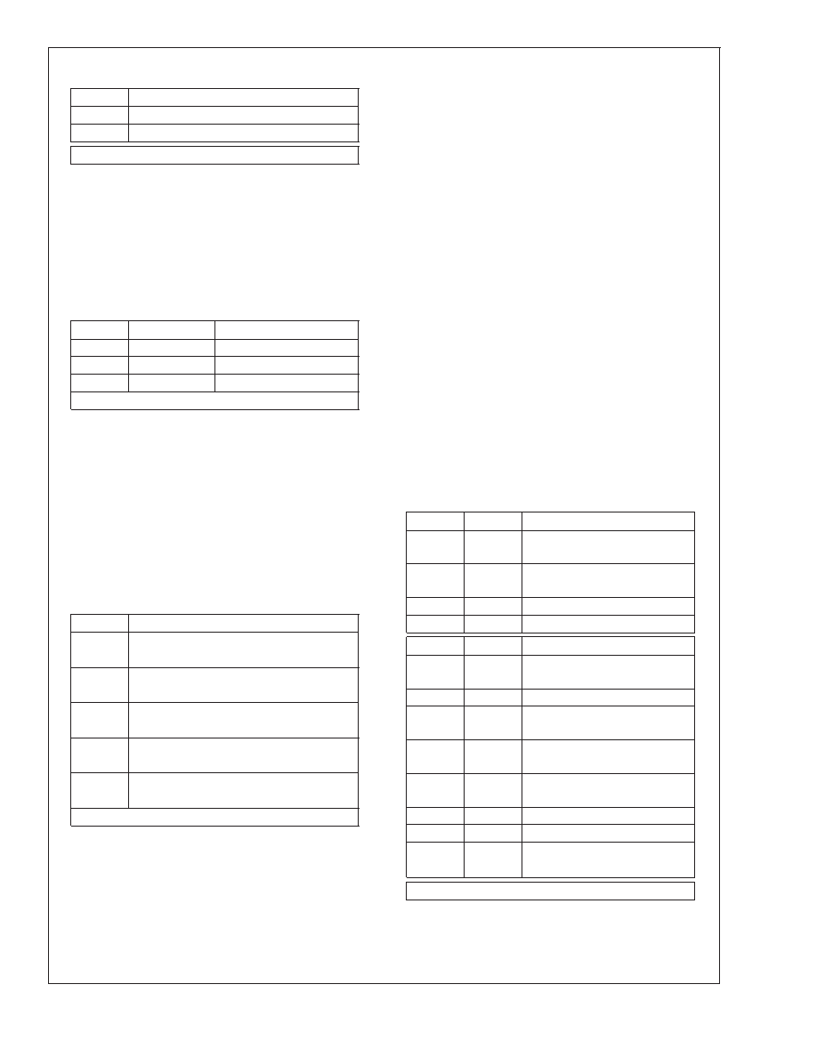
Register Descriptions (Continued)
SR2:SR0
Source for Right Channel ADC
6
Mono Mix
7
PHONE input
Default: 0000h
RECORD GAIN REGISTER (1Ch)
This register controls the input levels for both channels of the
stereo ADC. The inputs come from the Record Select Mux
and are selected via the Record Select Control register, 1Ah.
The gain of each channel can be individually programmed
from 0dB to +22.5 dB in 1.5 dB steps. Both channels can
also be muted by setting the MSB to 1.
Record Gain Register (1Ch)
Mute
Gx3:Gx0
Function
0
1111
22.5 dB gain
0
0000
0 dB gain
1
XXXX
*mute
Default: 8000h
GENERAL PURPOSE REGISTER (20h)
This register controls many miscellaneous functions imple-
mented on the LM4549B. The miscellaneous control bits
include POP which allows the DAC output to bypass the
National 3D Sound circuitry, 3D which enables or disables
the National 3D Sound circuitry, MIX which selects the MO-
NO_OUT source, MS which controls the Microphone Selec-
tion mux and LPBK which connects the output of the stereo
ADC to the input of the stereo DAC. LPBK provides a
mixed-mode analog and digital loopback path between ana-
log inputs and analog outputs. This is an 18 bit digital loop-
back at 48 kHz, bypassing the SRC logic, even if a sample
rate other than 48 kHz is selected.
BIT
Function
POP
PCM Out Path:
*0 = 3D allowed
1 = 3D bypassed
3D
National 3D Sound:
*0 = off
1= on
MIX
Mono output select:
*0 = Mix
1 = Mic
MS
Mic select:
*0 = MIC1
1 = MIC2
LPBK
ADC/DAC Loopback:
*0 = No Loopback
1 = Loopback
Default: 0000h
3D CONTROL REGISTER (22h)
This read-only (0101h) register indicates, in accordance with
the AC ’97 Rev 2.1 Specification, the fixed depth and center
characteristics of the National 3D Sound stereo enhance-
ment.
POWERDOWN CONTROL / STATUS REGISTER (26h)
This read/write register is used both to monitor subsystem
readiness and also to program the LM4549B powerdown
states. The 4 LSBs indicate status and 7 of the 8 MSBs
control powerdown.
The 4 LSBs of this register indicate the status of the 4 audio
subsections of the codec: Reference voltage, Analog mixers
and amplifiers, DAC section, ADC section. When the "Codec
Ready" indicator bit in the AC Link Input Frame (SDATA_IN:
slot 0, bit 15) is a "1", it indicates that the AC Link and AC ’97
registers are in a fully operational state and that control and
status information can be transferred. It does NOT indicate
that the codec is ready to send or receive audio PCM data or
to pass signals through the analog I/O and mixers. To deter-
mine that readiness, the Controller must check that the 4
LSBs of this register are set to “1” indicating that the appro-
priate audio subsections are ready.
The powerdown bits PR0 – PR5 control internal subsections
of the codec. They are implemented in compliance with AC
’97 Rev 2.1 to support the standard device power manage-
ment states D0 – D3 as defined in the ACPI and PCI Bus
Power Management Specification.
PR0 controls the powerdown state of the ADC and associ-
ated sampling rate conversion circuitry. PR1 controls power-
down for the DAC and the DAC sampling rate conversion
circuitry. PR2 powers down the mixer circuits (MIX1, MIX2,
National 3D Sound, Mono Out, Line Out). PR3 powers down
V
REF in addition to all the same mixer circuits as PR2. PR4
powers down the AC Link digital interface – see Figure 8 for
signal powerdown timing. PR5 disables internal clocks. PR6
is not used. EAPD controls the External Amplifier Power-
Down bit.
BIT#
BIT
Function: Status
0
ADC
1 = ADC section ready to
transmit data
1
DAC
1 = DAC section ready to
accept data
2
ANL
1 = Analog mixers ready
3
REF
1 = V
REF is up to nominal level
BIT#
BIT
Function: Powerdown
8
PR0
1 = Powerdown ADCs and
Record Select Mux
9
PR1
1 = Powerdown DACs
10
PR2
1 = Powerdown Analog Mixer
(V
REF still on)
11
PR3
1 = Powerdown Analog Mixer
(V
REF off)
12
PR4
1 = Powerdown AC Link digital
interface (BIT_CLK off)
13
PR5
1 = Disable Internal Clock
14
PR6
Not Used
15
EAPD
External Amplifier PowerDown
*0 = Set EAPD Pin to 0 (pin 47)
Default: 000Fh If ready; otherwise 000Xh
EXTENDED AUDIO ID REGISTER (28h)
This read-only (X001h) register identifies which AC ’97 Ex-
tended Audio features are supported. The LM4549B features
VRA (Variable Rate Audio) and ID1, ID0 (Multiple Codec
LM4549B
www.national.com
23
相關PDF資料 |
PDF描述 |
|---|---|
| LM4550BVH/NOPB | LM4550B AC '97 Rev 2.1 Multi-Channel Audio Codec with Stereo Headphone Amplifier, Sample Rate Conversion and National 3D Sound; Package: LQFP; No of Pins: 48; Qty per Container: 250/Tray |
| LM4550BVHX/NOPB | LM4550B AC '97 Rev 2.1 Multi-Channel Audio Codec with Stereo Headphone Amplifier, Sample Rate Conversion and National 3D Sound; Package: LQFP; No of Pins: 48; Qty per Container: 1000/Reel |
| LM4562NA/NOPB | LM4562 Dual High Performance, High Fidelity Audio Operational Amplifier; Package: MDIP; No of Pins: 8; Qty per Container: 40/Rail |
| LM45BIM3/NOPB | LM45 SOT-23 Precision Centigrade Temperature Sensors; Package: SOT-23; No of Pins: 3; Qty per Container: 1000/Reel |
| LM45BIM3X/NOPB | LM45 SOT-23 Precision Centigrade Temperature Sensors; Package: SOT-23; No of Pins: 3; Qty per Container: 3000/Reel |
相關代理商/技術參數(shù) |
參數(shù)描述 |
|---|---|
| LM4549VH | 制造商:Texas Instruments 功能描述: |
| LM4549VHX | 制造商:Texas Instruments 功能描述: |
| LM4550 | 制造商:NSC 制造商全稱:National Semiconductor 功能描述:AC ’97 Rev 2.1 Multi-Channel Audio Codec with Stereo Headphone Amplifier, Sample Rate Conversion and National 3D Sound |
| LM4550B | 制造商:NSC 制造商全稱:National Semiconductor 功能描述:AC 97 Rev 2.1 Multi-Channel Audio Codec with Stereo Headphone Amplifier, Sample Rate Conversion and National 3D Sound |
| LM4550BVH | 功能描述:接口—CODEC RoHS:否 制造商:Texas Instruments 類型: 分辨率: 轉(zhuǎn)換速率:48 kSPs 接口類型:I2C ADC 數(shù)量:2 DAC 數(shù)量:4 工作電源電壓:1.8 V, 2.1 V, 2.3 V to 5.5 V 最大工作溫度:+ 85 C 安裝風格:SMD/SMT 封裝 / 箱體:DSBGA-81 封裝:Reel |
發(fā)布緊急采購,3分鐘左右您將得到回復。