- 您現(xiàn)在的位置:買賣IC網(wǎng) > PDF目錄385474 > LM1391 (National Semiconductor Corporation) LM1391 Phase-Locked Loop PDF資料下載
參數(shù)資料
| 型號: | LM1391 |
| 廠商: | National Semiconductor Corporation |
| 英文描述: | LM1391 Phase-Locked Loop |
| 中文描述: | LM1391鎖相環(huán) |
| 文件頁數(shù): | 2/6頁 |
| 文件大小: | 131K |
| 代理商: | LM1391 |

Absolute Maximum Ratings
If Military/Aerospace specified devices are required,
please contact the National Semiconductor Sales
Office/Distributors for availability and specifications.
Supply Current
40 mA
DC
40 V
DC
30 mA
DC
5.0 Vp-p
Output Voltage
Output Current
Sync Input Voltage (Pin 3)
Flyback Input Voltage (Pin 4)
5.0 Vp-p
Power Dissipation (Package Limitation)
Plastic Package (Note 1)
1000 mW
0
§
C to
a
70
§
C
b
65
§
C to
a
150
§
C
Operating Temperature Range (Ambient)
Storage Temperature Range
Lead Temperature (Soldering, 10 sec.)
260
§
C
Electrical Characteristics
T
A
e
25
§
C (see test circuit, all switches in position 1)
Parameter
Conditions
Min
Typ
Max
Units
Regulated Voltage (Pin 6)
I
6
e
22 mA
DC
8.0
8.6
9.2
V
DC
Supply Current (Pin 6)
20
mA
DC
Collector-Emitter Saturation Voltage
of Output Transistor (Pin 1)
I
C1
e
20 mA
0.30
0.40
V
DC
Pin 4 Voltage
2.0
V
DC
Oscillator Pull-in Range
Adjust R
H
g
300
Hz
Oscillator Hold-in Range
Adjust R
H
g
900
Hz
Static Phase Error
D
f
e
300 Hz
0.5
m
s
Free-running Frequency Supply
Dependance
S1 in position 2
g
3.0
Hz/V
DC
Phase Detector Leakage (Pin 5)
All switches in position 2
g
1.0
m
A
Sync Input Voltage (Pin 3)
2.0
5.0
Vp-p
Sawtooth Input Voltage (Pin 4)
1.0
3.0
Vp-p
Maximum Oscillator Frequency
500
kHz
Note 1:
For operation in ambient temperatures above 25
§
C, the device must be derated based on a 150
§
C maximum junction temperature and a thermal resistance
of 120
§
C/W junction to ambient.
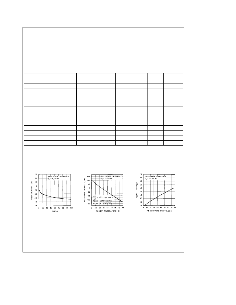
Typical Performance Characteristics
Time
Frequency Drift vs Warm-Up
Frequency vs Temperature
Voltage
Output Duty Cycle vs V
M
TL/H/7889–3
2
相關(guān)PDF資料 |
PDF描述 |
|---|---|
| LM1391N | LM1391 Phase-Locked Loop |
| LM140JAN | Three Terminal Positive Regulators |
| LM143 | High Voltage Operational Amplifier |
| LM343 | High Voltage Operational Amplifier |
| LM343H | High Voltage Operational Amplifier |
相關(guān)代理商/技術(shù)參數(shù) |
參數(shù)描述 |
|---|---|
| LM1391 MOT83 | 制造商:Motorola 功能描述:LM1391N |
| LM1391MOT83 | 制造商:Motorola 功能描述:LM1391N |
| LM1391N | 制造商:NSC 制造商全稱:National Semiconductor 功能描述:LM1391 Phase-Locked Loop |
| LM1391N/A+ | 制造商:未知廠家 制造商全稱:未知廠家 功能描述:Analog Phase-Locked Loop |
| LM1391N/B+ | 制造商:未知廠家 制造商全稱:未知廠家 功能描述:Analog Phase-Locked Loop |
發(fā)布緊急采購,3分鐘左右您將得到回復(fù)。