- 您現(xiàn)在的位置:買(mǎi)賣(mài)IC網(wǎng) > PDF目錄358759 > LC72336 (Sanyo Electric Co.,Ltd.) Single-Chip Microcontrollers with Built-In LCD Driver and PLL Circuits PDF資料下載
參數(shù)資料
| 型號(hào): | LC72336 |
| 廠(chǎng)商: | Sanyo Electric Co.,Ltd. |
| 英文描述: | Single-Chip Microcontrollers with Built-In LCD Driver and PLL Circuits |
| 中文描述: | 單片微控制器,內(nèi)置在LCD驅(qū)動(dòng)和PLL電路 |
| 文件頁(yè)數(shù): | 12/16頁(yè) |
| 文件大小: | 185K |
| 代理商: | LC72336 |
第1頁(yè)第2頁(yè)第3頁(yè)第4頁(yè)第5頁(yè)第6頁(yè)第7頁(yè)第8頁(yè)第9頁(yè)第10頁(yè)第11頁(yè)當(dāng)前第12頁(yè)第13頁(yè)第14頁(yè)第15頁(yè)第16頁(yè)
Continued from preceding page.
No. 5157-12/16
LC72336, 72338
Continued on next page.
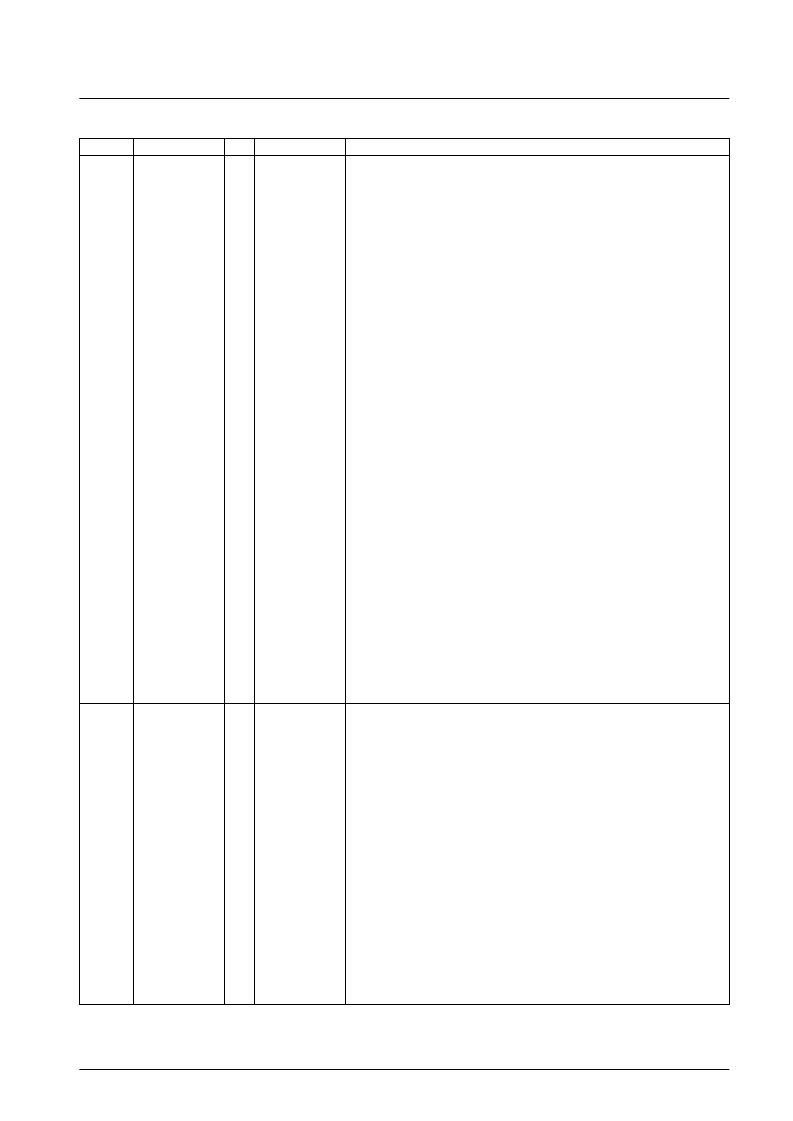
Pin No.
Symbol
I/O
I/O type
Function
35
34
33
32
30
29
28
27
S21/PF0
S22/PF1/SCK1
S23/PF2/SO1
S24/PF3/SI1
S25/PM0
S26/PM1
S27/PM2
S28/PM3
I/O
I/O
CMOS 3-value
output and
push-pull
CMOS 3-value
output and
push-pull
Shared-function LCD driver segment output, general-purpose I/O, and serial I/O port
The PF0 to PF3 inputs are Schmitt inputs.
The IOS instruction is used to switch between the LCD driver segment output, general-
purpose I/O, and serial I/O functions, and to switch between input and output for the
general-purpose input port function.
When used for segment output:
The function is specified in 4-bit units.
Segment output is specified with the IOS instruction (Pn = 0EH).
b0 = S21 to S24/PF0 to PF3
0 ... Segment output
1 ... PF0 to PF3 output
When used as a general-purpose I/O port:
Input or output can be specified in bit units (1-bit I/O).
The general-purpose I/O port function is specified with the IOS instruction (Pn = 0).
b1 = SI/O1
0 ... General-purpose port
1 ... SI/O port
Input or output is specified with the IOS instruction in bit units.
PF ... Pn = 5
0 ... Input
1 ... Output
When used as a serial I/O port:
The serial I/O port function is specified with the IOS instruction (Pn = 0).
The contents of the serial I/O data buffer can be saved and loaded with the INR and
OUTR instructions.
Note: Pin setup states when used as a serial I/O port:
PF0 ... General-purpose I/O
PF1 ... SCK1 output in internal clock mode
SCK1 input in external clock mode
PF2 ... SO1 output
PF3 ... SI1 input
In clock stop mode, if this port is used as a general-purpose I/O port or as a serial I/O
port, the pins go to the input disabled high-impedance state. If used for segment output,
the pins are fixed at the low level.
The segment output port function is selected after a power-on reset.
Shared-function LCD driver segment output and general-purpose I/O port
The IOS instruction is used to switch between the LCD driver segment output and the
general-purpose I/O functions, and to switch between input and output for the general-
purpose input port function.
When used for segment output:
The function is specified in 4-bit units.
Segment output is specified with the IOS instruction (Pn = 0EH).
b1 = S25 to S28/PM0 to PM3
0 ... Segment output
1 ... PF0 to PF3 output
When used as a general-purpose I/O port:
Input or output can be specified in bit units (1-bit I/O).
Input or output is specified with the IOS instruction in bit units.
PM ... Pn = 0CH
0 ... Input
1 ... Output
In clock stop mode, if this port is used as a general-purpose I/O port, the pins go to the
input disabled high-impedance state. If used for segment output, the pins are fixed at the
low level.
The segment output port function is selected after a power-on reset.
相關(guān)PDF資料 |
PDF描述 |
|---|---|
| LC7233N-8818 | Single-Chip PLL and Controller with LCD Driver(用于電子調(diào)諧的單片微控制器(帶LCD驅(qū)動(dòng)器和鎖相環(huán)電路 )) |
| LC7233N | Single-Chip PLL and Microcontroller with LCD Driver |
| LC7233 | Single-Chip PLL and Microcontroller with LCD Driver |
| LC72341G | Low-Voltage Single-Chip Microcontrollers with On-Chip PLL and LCD Driver Circuits(用于音頻設(shè)備的低電壓?jiǎn)纹⒖刂破鳎◣湘i相環(huán)電路和LCD驅(qū)動(dòng)器)) |
| LC72345 | Low-Voltage ETR Controller with On-Chip DC-DC Converter |
相關(guān)代理商/技術(shù)參數(shù) |
參數(shù)描述 |
|---|---|
| LC72338 | 制造商:SANYO 制造商全稱(chēng):Sanyo Semicon Device 功能描述:Single-Chip Microcontrollers with Built-In LCD Driver and PLL Circuits |
| LC7233N | 制造商:SANYO 制造商全稱(chēng):Sanyo Semicon Device 功能描述:Single-Chip PLL and Microcontroller with LCD Driver |
| LC7233N-8818 | 制造商:SANYO 制造商全稱(chēng):Sanyo Semicon Device 功能描述:Single-Chip PLL and Controller with LCD Driver |
| LC7234 | 制造商:SANYO 制造商全稱(chēng):Sanyo Semicon Device 功能描述:Single-Chip PLL and Microcontroller with LCD Driver |
| LC72341 | 制造商:SANYO 制造商全稱(chēng):Sanyo Semicon Device 功能描述:Low-Voltage Single-Chip Microcontrollers with On- Chip PLL and LCD Driver Circuits |
發(fā)布緊急采購(gòu),3分鐘左右您將得到回復(fù)。