- 您現(xiàn)在的位置:買(mǎi)賣(mài)IC網(wǎng) > PDF目錄383236 > L6275 (意法半導(dǎo)體) 5V DISK DRIVE SPINDLE & VCM, POWER & CONTROL “COMBO” PDF資料下載
參數(shù)資料
| 型號(hào): | L6275 |
| 廠商: | 意法半導(dǎo)體 |
| 英文描述: | 5V DISK DRIVE SPINDLE & VCM, POWER & CONTROL “COMBO” |
| 中文描述: | 5V的磁盤(pán)驅(qū)動(dòng)器主軸 |
| 文件頁(yè)數(shù): | 8/17頁(yè) |
| 文件大小: | 109K |
| 代理商: | L6275 |
第1頁(yè)第2頁(yè)第3頁(yè)第4頁(yè)第5頁(yè)第6頁(yè)第7頁(yè)當(dāng)前第8頁(yè)第9頁(yè)第10頁(yè)第11頁(yè)第12頁(yè)第13頁(yè)第14頁(yè)第15頁(yè)第16頁(yè)第17頁(yè)
SERIAL PORTOPERATION
The serial port interface is a bi-directional port for reading and writing programming data from/to the in-
ternal registers of this device. For data transfers SDEN* is brought high, serial data is presented at the
SDATA pin, and a serial clock is applied to the SCLK pin. After the SDEN* goes high , the first 16 pulses
applied to the SCLK pin will shift the data presented at the SDATA pin into an internal shift register on
the rising edge of each clock. An internal counter prevents more than 16 bits from being shifted into the
register. The data in the shift register is latched after the 16th SCLK pulse. If less than 16 clock pulses
are providedbeforeSDEN* goes low, thedata transferis aborted.
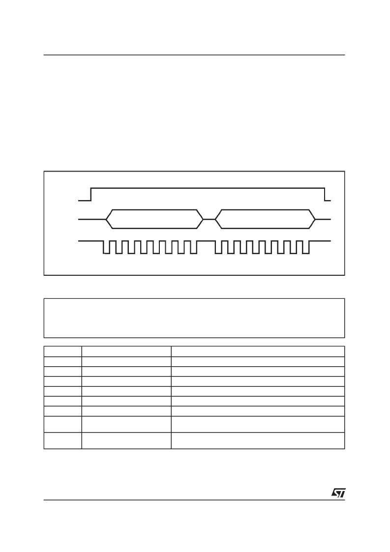
All transfers are shifted into the serial port LSB first. The first byte of the transfer is for R/W and address
and instructioninformation.The first bit is R/W instructionbit,0 is for WRITE and 1 is for READ.
Following 7 bitsare Address.
INSTRUCTION, 1 BIT
ADDRESS, 7 BITS
D98IN845
DATA, 8 BITS
SDEN
SCLK
SDATA
Figure 2. SerialPort Data TransferFormat.
INTERNALREGISTER DEFINITION
Reg:
Name:
Type:
Address:
0
VCM DAC (High) Register
Write only
0Eh
BIT
LABEL
DESCRIPTION
0
VDAC BIT8
VCM DAC bit 8
1
VDAC BIT9
VCM DAC bit 9
2
VDAC BIT10
VCM DAC bit 10
3
VDAC BIT11
VCM DAC bit 11
4
VDAC BIT12
VCM DAC bit 12
5
VDAC BIT13
MSB resistorladder of the 14 bit VCM DAC
6
PSM/LINEAR
Selects Voice Coil PSM or Linear Output Current Control. 1=PSM
0=Linear.
7
VCM_CAL
VCM calibration. 1 = Enables VCM control circuits and tristates
VCM power transistors.
L6275
8/17
相關(guān)PDF資料 |
PDF描述 |
|---|---|
| L6280 | THREE CHANNELS MULTIPOWER DRIVER SYSTEM |
| L6285 | 3 CHANNELS MULTIPOWER SYSTEM |
| L6285S | 3 CHANNELS MULTIPOWER SYSTEM |
| L6316 | 4-CHANNEL LOW POWER PREAMPLIFIER |
| L634 | THREE PHASE MOTOR DRIVER |
相關(guān)代理商/技術(shù)參數(shù) |
參數(shù)描述 |
|---|---|
| L6278-1.2 | 制造商:STMicroelectronics 功能描述:ELECTRONIC COMPONENT |
| L6280 | 制造商:STMICROELECTRONICS 制造商全稱(chēng):STMicroelectronics 功能描述:THREE CHANNELS MULTIPOWER DRIVER SYSTEM |
| L6281B12D | 制造商:ST MICRO 功能描述:New |
| L6282-3.2E | 制造商:STMicroelectronics 功能描述:L6282-3.2E |
| L6283-1.2 | 制造商:STMicroelectronics 功能描述:ELECTRONIC COMPONENT |
發(fā)布緊急采購(gòu),3分鐘左右您將得到回復(fù)。