- 您現(xiàn)在的位置:買賣IC網(wǎng) > PDF目錄383235 > L6232E (意法半導體) Spindle Driver(主軸驅(qū)動器) PDF資料下載
參數(shù)資料
| 型號: | L6232E |
| 廠商: | 意法半導體 |
| 英文描述: | Spindle Driver(主軸驅(qū)動器) |
| 中文描述: | 主軸驅(qū)動器(主軸驅(qū)動器) |
| 文件頁數(shù): | 6/10頁 |
| 文件大小: | 113K |
| 代理商: | L6232E |
mize noise effects(EMI). LIN Vref and PWM Vref
are connected to a comparator whose output is
fed to the logic . The upper and lower DMOS
driver slew-rates are controlled by the internal
logic.
In PWM mode, the upper driver is turned-offwhen
the motor current reaches the intended value. An
internal One-Shot pulse determines the lenght of
time the upper driver stays off before turning on
again. The pulse width, and thus the cutoff time
(toff), is configurable by means of the external RC
network connectedto the RC pin. (see Fig. 2). The
resistor at the RC pin, therefore determines both
the driver output slew-rate during linear mode and
the off-time constantduring PWM. The lower driver
is always on during PWM mode of operation; an
on-chip 2
μ
s mask can prevent the beginning of a
new cutofftime becauseof transientcurrent spikes
causedby theupperdriversturn-on.
The driving mode is determined by the smaller of
the two controlling input voltages. In a typical ap-
plication the motor start-up would occur in PWM
mode to limit power dissipation, with on-speed
control then performedin linearmode.
Thermal protection circuitry will shut-off all drivers
when the chip junction temperature exceeds the
threshold temperature. A small amount of hyster-
esis is included to prevent rapid on/off cycling of
the power stages.
Additionalprotectionis providedagainstdriver input
combinationswhere the upper and lower drivers of
a half bridge are turned on simultaneusly, resulting
in a short from supply to ground.The chiplogic will
causeboththe upperand lower drivers involvedto
turn-off.(see Table1)
APPLICATION INFORMATION
A typical application configuration of the L6232E
driving a three-phase brushless DC motor is
shown in Fig.3. The spindle motor is a 4 ohm-
2mH per phase, star connected. This load re-
quires a suitable compensation of the linear con-
trol loop that can be achieved by Rc= 10 Kohm
and Cc= 10nF (R3;C8). Changing the motor char-
acteristics, the RcCc network would be modified
for the best performances of the system. At the
start-up the spindle is driven in PWM mode fixed
toff time.
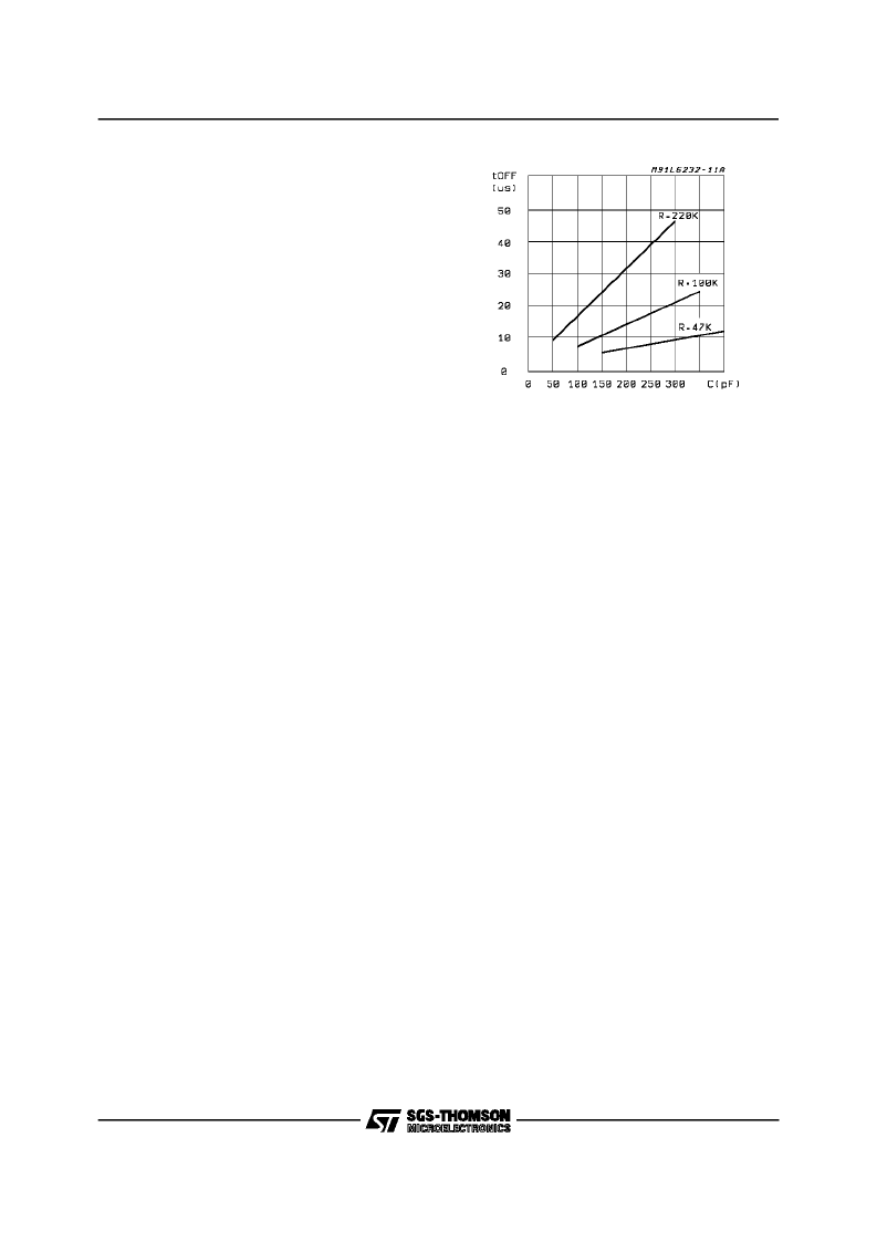
The off-time is calculatedby the formula:
toff = 0.69 R2 C7
See fig.2 for a quick choice of the needed capaci-
tor, after the resistor has been fixed. The value of
the resistor defines the rate at which the upper
and lower drivers turn-off during linear mode op-
eration to avoid EMI effects. During turn-off, the
slew rate is constant for the sink stage, while it
has a varying slope for the source stage because
of the non linear change of the gate to source im-
pedance of the DMOS transistor. Practically, the
slowest slew rate is obtainedat the sink transistor
switch-off time (see fig. 5), then it increases dur-
ing the first period of the source transistor switch-
off (source,1st) and it becomes the fastest during
the final portion of the turn-off duration (source,
2nd). The PWM to linear mode of operation is
switched by decreasing the LIN Vref level under
the PWM Vref value that could be fixed and cal-
culatedby:
PWMVref = 4 Rs Ip
where Ip is the peak chopping current in the mo-
tor windings. Of course, when the required RPM
is reached, it become of no need a strong torque
and the LIN Vref starting from a value higher than
the calculated PWM Vref, decreases to the value
:
LINVref = 4 Rs Im
whereIm, smaller thanIp, is the neededmotor cur-
rent to keep constantspin. This last reference volt-
age is generally a PLL output driven by speed
transducers coupled to the spindle (like Hall effect
sensors or BEMF processors). To drive the upper
DMOS and during the brake function a voltage
higher than the supply Vs is needed. The charge
pump integrated in the L6232E keeps C3 at the
correct voltage. To guarantee efficient braking of
the motor , C3 must be chosenof adeguatequality
(very high equivalent parallel resistance). C4 can
be a ceramic disk capacitor . The typical applica-
tion od the L6232E is in HDD systems on which
thereis the need to park theRead-Write Heads be-
fore the motor braking. This behavior is possible
with the circuit of Fig.3. At Power Supply switch-off
(see Fig. 1), VP falls down and drives down the
BRK input (Active Low). D1 insulates the L6232E
from the power suppy output while the power out-
put stage is switched in a high impedance state.
The spindlemotor actingas a three-phasealterna-
tor supplies the Heads voice coil motor driven
through integrateddiodesthatrectifie the EMF. Af-
ter a delay longer than the parking time, the lower
outputDMOS are switched-on andthe spindlemo-
tor is braked. The brake delay time is tipically 150
msecandit is definedby :
Figure2:
Typicalt
off
vs. Capacityof C
L6232E
6/10
相關(guān)PDF資料 |
PDF描述 |
|---|---|
| L6234 | Three Phase Motor Driver(三相電機驅(qū)動器) |
| L6237 | 5V Spindle Motor Driver(5V主軸電機驅(qū)動器) |
| L6238S | 12V Sensorless Spindle Motor Controller(主軸馬達控制器) |
| L6238 | Sensorless Spindle Motor Driver(無傳感器主軸電機驅(qū)動器) |
| L6239 | 12V Disk Drive Spindle Driver(12V磁盤驅(qū)動主軸驅(qū)動器) |
相關(guān)代理商/技術(shù)參數(shù) |
參數(shù)描述 |
|---|---|
| L6233 | 制造商:未知廠家 制造商全稱:未知廠家 功能描述:Analog IC |
| L6233P | 制造商:未知廠家 制造商全稱:未知廠家 功能描述:Analog IC |
| L6234 | 功能描述:馬達/運動/點火控制器和驅(qū)動器 Three Phase Motor RoHS:否 制造商:STMicroelectronics 產(chǎn)品:Stepper Motor Controllers / Drivers 類型:2 Phase Stepper Motor Driver 工作電源電壓:8 V to 45 V 電源電流:0.5 mA 工作溫度:- 25 C to + 125 C 安裝風格:SMD/SMT 封裝 / 箱體:HTSSOP-28 封裝:Tube |
| L6234 | 制造商:STMicroelectronics 功能描述:IC HALF BRIDGE DRIVER TRIPLE 6234 |
| L6234D | 制造商:STMicroelectronics 功能描述: |
發(fā)布緊急采購,3分鐘左右您將得到回復。