- 您現(xiàn)在的位置:買賣IC網(wǎng) > PDF目錄384533 > ISL97650ARTZ-TK (INTERSIL CORP) 4-Channel Integrated LCD Supply PDF資料下載
參數(shù)資料
| 型號: | ISL97650ARTZ-TK |
| 廠商: | INTERSIL CORP |
| 元件分類: | 顯示驅(qū)動(dòng)器 |
| 英文描述: | 4-Channel Integrated LCD Supply |
| 中文描述: | LIQUID CRYSTAL DISPLAY DRIVER, PQCC36 |
| 封裝: | 6 X 6 MM, ROHS COMPLIANT, PLASTIC, MO-220WJJD-1, TMLFP-36 |
| 文件頁數(shù): | 11/20頁 |
| 文件大小: | 333K |
| 代理商: | ISL97650ARTZ-TK |
11
FN9198.3
November 28, 2006
Applications Information
The ISL97650 provides a complete power solution for TFT
LCD applications. The system consists of one boost
converter to generate A
VDD
voltage for column drivers, one
buck converter to provide voltage to logic circuit in the LCD
panel, one integrated V
ON
charge pump and one V
OFF
linear-regulator controller to provide the voltage to row
drivers. This part also integrates V
ON
-slice circuit which can
help to optimize the picture quality. With the high output
current capability, this part is ideal for big screen LCD TV
and monitor panel application.
The integrated boost converter and buck converter operate
at 1.2MHz which can allow to use multilayer ceramic
capacitors and low profile inductor which result in low cost,
compact and reliable system. The logic output voltage is
independently enabled to give flexibility to the system
designers.
Boost Converter
The boost converter is a current mode PWM converter
operating at a fixed frequency of 1.2MHz. It can operate in
both discontinuous conduction mode (DCM) at light load and
continuous mode (CCM). In continuous current mode,
current flows continuously in the inductor during the entire
switching cycle in steady state operation. The voltage
conversion ratio in continuous current mode is given by:
Where D is the duty cycle of the switching MOSFET.
The boost converter uses a summing amplifier architecture
consisting of gm stages for voltage feedback, current
feedback and slope compensation. A comparator looks at
the peak inductor current cycle by cycle and terminates the
PWM cycle if the current limit is reached.
An external resistor divider is required to divide the output
voltage down to the nominal reference voltage. Current
drawn by the resistor network should be limited to maintain
the overall converter efficiency. The maximum value of the
resistor network is limited by the feedback input bias current
and the potential for noise being coupled into the feedback
pin. A resistor network in the order of 60k
Ω
is recommended.
The boost converter output voltage is determined by the
following equation:
The current through the MOSFET is limited to 2.6Apeak.
This restricts the maximum output current (average) based
on the following equation:
Where
Δ
IL is peak to peak inductor ripple current, and is set
by:
where f
s
is the switching frequency(1.2MHz).
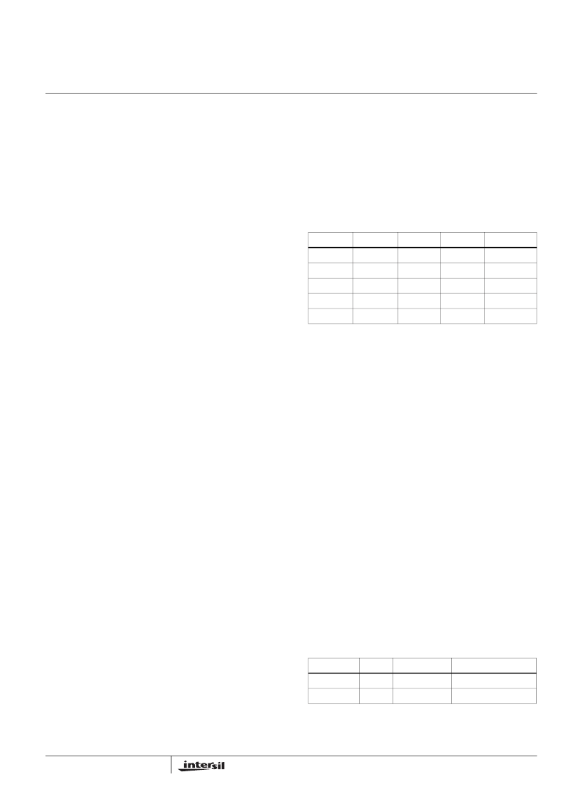
The following table gives typical values (margins are
considered 10%, 3%, 20%, 10% and 15% on V
IN
, V
O
, L, fs
and I
OMAX
):
The minimum duty cycle of the ISL97650 is 25%. When the
operating duty cycle is lower than the minimum duty cycle,
the part will not switch in some cycles randomly, which will
cause some LX pulses to be skipped. In this case, LX pulses
are not consistent any more, but the output voltage (A
VDD
) is
still regulated by the ratio of R3 and R5. This relationship is
given by Equation 2. Because some LX pulses are skipped,
the ripple current in the inductor will become bigger. Under
the worst case, the ripple current will be from 0 to the
threshold of the current limit. In turn, the bigger ripple current
will increase the output voltage ripple. Hence, it will need
more output capacitors to keep the output ripple at the same
level. When the input voltage equals, or is larger than, the
output voltage, the boost converter will stop switching. The
boost converter is not regulated any more, but the part will
still be on and other channels are still regulated. The typical
waveforms of pulse-skipping mode are shown in the "Typical
Performance Curves" section.
Boost Converter Input Capacitor
An input capacitor is used to suppress the voltage ripple
injected into the boost converter. The ceramic capacitor with
capacitance larger than 10μF is recommended. The voltage
rating of input capacitor should be larger than the maximum
input voltage. Some capacitors are recommended in Table 2
for input capacitor.
V
IN
------------------
D
-----–
=
(EQ. 1)
A
VDD
R
--------------------
R
5
+
5
V
FBB
×
=
(EQ. 2)
I
OMAX
I
LMT
Δ
I
L
2
--------
–
V
V
O
---------
×
=
(EQ. 3)
TABLE 1. MAXIMUM OUTPUT CURRENT CALCULATION
V
IN
(V)
V
O
(V)
L (μH)
f
s
(MHz)
I
OMAX
(mA)
5
9
6.8
1.2
1138
5
12
6.8
1.2
777
4
15
6.8
1.2
560
12
15
6.8
1.2
1345
12
18
6.8
1.2
998
TABLE 2. BOOST CONVERTER INPUT CAPACITOR
RECOMMENDATION
CAPACITOR
SIZE
VENDOR
PART NUMBER
10μF/25V
1210
TDK
C3225X7R1E106M
10μF/25V
1210
Murata
GRM32DR61E106K
Δ
I
L
V
---------
D
f
S
----
×
=
(EQ. 4)
ISL97650
相關(guān)PDF資料 |
PDF描述 |
|---|---|
| ISL97652 | 4-Channel Integrated LCD Supply with Dual VCOM Amplifiers |
| ISL97652IRZ | 4-Channel Integrated LCD Supply with Dual VCOM Amplifiers |
| ISL97652IRZ-T | 4-Channel Integrated LCD Supply with Dual VCOM Amplifiers |
| ISL97652IRZ-TK | 4-Channel Integrated LCD Supply with Dual VCOM Amplifiers |
| ISL97653A | 5-Channel Integrated LCD Supply |
相關(guān)代理商/技術(shù)參數(shù) |
參數(shù)描述 |
|---|---|
| ISL97650BIRTZ-T | 功能描述:直流/直流開關(guān)調(diào)節(jié)器 4-CH INTEGRTD LCD SUPPLY 36LD TQFN RoHS:否 制造商:International Rectifier 最大輸入電壓:21 V 開關(guān)頻率:1.5 MHz 輸出電壓:0.5 V to 0.86 V 輸出電流:4 A 輸出端數(shù)量: 最大工作溫度: 安裝風(fēng)格:SMD/SMT 封裝 / 箱體:PQFN 4 x 5 |
| ISL97650BIRTZ-TK | 功能描述:直流/直流開關(guān)調(diào)節(jié)器 4-CH INTEGRTD LCD SUPPLY 36LD TQFN RoHS:否 制造商:International Rectifier 最大輸入電壓:21 V 開關(guān)頻率:1.5 MHz 輸出電壓:0.5 V to 0.86 V 輸出電流:4 A 輸出端數(shù)量: 最大工作溫度: 安裝風(fēng)格:SMD/SMT 封裝 / 箱體:PQFN 4 x 5 |
| ISL97651ARTZ | 制造商:Intersil Corporation 功能描述: |
| ISL97651ARTZ-T | 功能描述:顯示驅(qū)動(dòng)器和控制器 ISL97651ARTZ 4-CH IN TEGRTD LCD SUPY RoHS:否 制造商:Panasonic Electronic Components 工作電源電壓:2.7 V to 5.5 V 最大工作溫度: 安裝風(fēng)格:SMD/SMT 封裝 / 箱體:QFN-44 封裝:Reel |
| ISL97651ARTZ-TK | 功能描述:顯示驅(qū)動(dòng)器和控制器 ISL97651ARTZ 4-CH IN TEGRTD LCD SUPY 1K RoHS:否 制造商:Panasonic Electronic Components 工作電源電壓:2.7 V to 5.5 V 最大工作溫度: 安裝風(fēng)格:SMD/SMT 封裝 / 箱體:QFN-44 封裝:Reel |
發(fā)布緊急采購,3分鐘左右您將得到回復(fù)。