- 您現(xiàn)在的位置:買賣IC網(wǎng) > PDF目錄299229 > ISD1420XC5006 (WINBOND ELECTRONICS CORP) 20 SEC, SPEECH SYNTHESIZER WITH RCDG, UUC25 PDF資料下載
參數(shù)資料
| 型號: | ISD1420XC5006 |
| 廠商: | WINBOND ELECTRONICS CORP |
| 元件分類: | 音頻合成 |
| 英文描述: | 20 SEC, SPEECH SYNTHESIZER WITH RCDG, UUC25 |
| 封裝: | DIE-25 |
| 文件頁數(shù): | 31/33頁 |
| 文件大?。?/td> | 318K |
| 代理商: | ISD1420XC5006 |
第1頁第2頁第3頁第4頁第5頁第6頁第7頁第8頁第9頁第10頁第11頁第12頁第13頁第14頁第15頁第16頁第17頁第18頁第19頁第20頁第21頁第22頁第23頁第24頁第25頁第26頁第27頁第28頁第29頁第30頁當前第31頁第32頁第33頁
ISD1400 SERIES
Publication Release Date: November 16, 2005
- 7 -
Revision 1.3
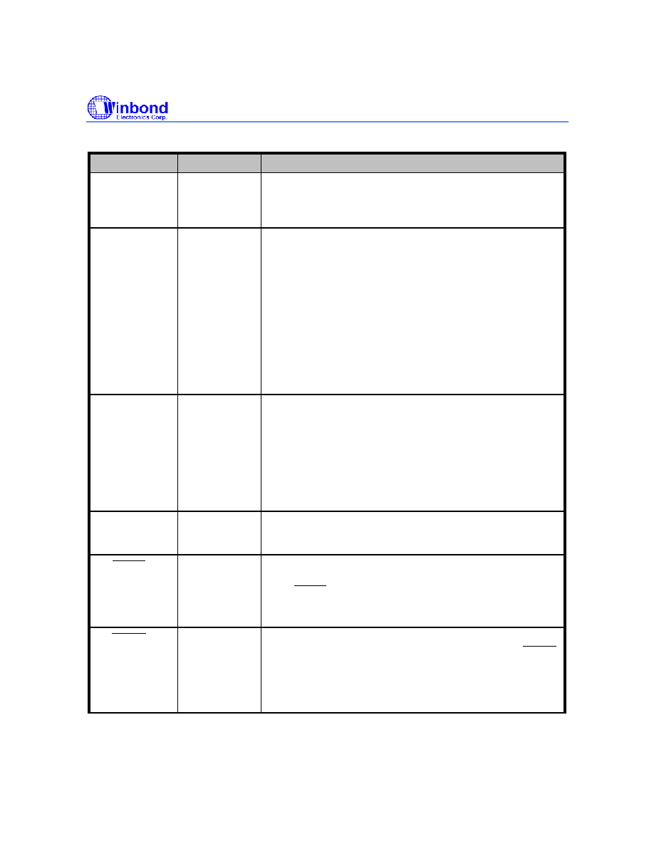
PIN NAME
PIN NO
FUNCTION
MIC REF
18
Microphone Reference
: The MIC REF input is the inverting
input to the microphone preamplifier. This provides a noise-
canceling or common-mode rejection input to the device
when connected to a differential microphone.
AGC
19
Automatic Gain Control (AGC)
: The AGC dynamically
adjusts the gain of the preamplifier to compensate for the
wide range of microphone input levels. The AGC allows the
full range of sound, from whispers to loud sounds, to be
recorded with minimal distortion. The “attack” time is
determined by the time constant of a 5 K internal resistance
and an external capacitor (C6 on the schematic of section 11,
Figure 5) connected from the AGC pin to VSSA analog ground.
The “release” time is determined by the time constant of an
external resistor (R5) and an external capacitor (C6)
connected in parallel between the AGC pin and VSSA analog
ground. Nominal values of 470 K and 4.7 F give
satisfactory results in most cases.
ANA IN
20
Analog Input
: The analog input pin transfers its signal to the
chip for recording. For microphone inputs, the ANA OUT pin
should be connected via an external capacitor to the ANA IN
pin. This capacitor value, together with the 3.0 K input
impedance of ANA IN, is selected to give additional cutoff at
the low-frequency end of the voice passband. If the desired
input is derived from a source other than a microphone, the
signal can be fed, capacitively coupled, into the ANA IN pin
directly.
ANA OUT
21
Analog Output
: This pin provides the preamplifier output to
the user. The voltage gain of the preamplifier is determined
by the voltage level at the AGC pin.
PLAYL
[2]
23
Playback, Level-Activated
: When this input signal is held
LOW, a playback cycle is initiated, and playback continues
until PLAYL is pulled HIGH, or an EOM marker is detected.
The device automatically powers down and enters into
standby mode upon completion of a playback cycle.
PLAYE
[2]
24
Playback, Edge-Activated
: When a LOW-going transition is
input to this pin, a playback cycle begins. Taking PLAYE
HIGH during a playback cycle will not terminate the current
cycle. Playback continues until an EOM is encountered. Upon
completion of a playback cycle, the device automatically
powers down and enters into standby mode.
相關(guān)PDF資料 |
PDF描述 |
|---|---|
| ISD33150ED | 157.1 SEC, SPEECH SYNTHESIZER WITH RCDG, PDSO28 |
| ISD33150EI | 162 SEC, SPEECH SYNTHESIZER WITH RCDG, PDSO28 |
| ISD33150E | 155.6 SEC, SPEECH SYNTHESIZER WITH RCDG, PDSO28 |
| ISD33150PD | 157.1 SEC, SPEECH SYNTHESIZER WITH RCDG, PDIP28 |
| ISD33150PI | 162 SEC, SPEECH SYNTHESIZER WITH RCDG, PDIP28 |
相關(guān)代理商/技術(shù)參數(shù) |
參數(shù)描述 |
|---|---|
| ISD1420XI | 制造商:未知廠家 制造商全稱:未知廠家 功能描述:Single-Chip Voice Record/Playback Devices 16-and 20-Second Durations |
| ISD1447AS1 | 制造商:ISAHAYA 制造商全稱:Isahaya Electronics Corporation 功能描述:FOR LOW FREQUENCY POWOR AMPLIFY APPLICATION SILICON NPN EPITAXIAL TYPE |
| ISD14B20 | 制造商:WINBOND 制造商全稱:Winbond 功能描述:SINGLE-CHIP, MULTIPLE-MESSAGE VOICE RECORD/PLAYBACK DEVICE 10.6- TO 32-SECONDS DURATION |
| ISD14B20X | 制造商:WINBOND 制造商全稱:Winbond 功能描述:SINGLE-CHIP, MULTIPLE-MESSAGE VOICE RECORD/PLAYBACK DEVICE 10.6- TO 32-SECONDS DURATION |
| ISD1506P | 制造商:未知廠家 制造商全稱:未知廠家 功能描述:Solid-State Recorder |
發(fā)布緊急采購,3分鐘左右您將得到回復(fù)。