- 您現(xiàn)在的位置:買賣IC網(wǎng) > PDF目錄384509 > IRPT1061A (International Rectifier) Power Module for 1 hp Motor Drives PDF資料下載
參數(shù)資料
| 型號: | IRPT1061A |
| 廠商: | International Rectifier |
| 英文描述: | Power Module for 1 hp Motor Drives |
| 中文描述: | 功率模塊電機(jī)驅(qū)動器1馬力 |
| 文件頁數(shù): | 2/12頁 |
| 文件大小: | 256K |
| 代理商: | IRPT1061A |
page 2
IRPT1061A
System Description
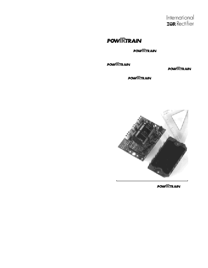
The IRPT1061A Pow er Module
The IRPT1061A power module, shown in figure 1, is a chip
and wire epoxy encapsulated module. It houses input rectifiers,
brake IGBT and freewheeling diode, output inverter, current
sense shunts and NTC thermistor. The 3-phase input bridge
rectifiers are rated at 800V. The inverter section uses 600V,
short circuit rated, ultrafast IGBTs and ultrafast freewheeling
diodes. Current sensing is achieved through 75 m
low
inductance shunts provided in the positive and negative DC bus
rail. The NTC thermistor provides temperature sensing
capability. The lead spacing on the power module meets UL840
pollution level 3 requirements.
The power circuit and layout within the module are carefully
designed to minimize inductance in the power path, to reduce
noise during inverter operation and to improve the inverter
efficiency. The Driver-
Plus
Board required to run the inverter
can be soldered to the power module pins, thus minimizing
assembly and alignment. The power module is designed to be
mounted to a heat sink with two screw mount positions, in order
to insure good thermal contact between the module substrate and
the heat sink.
and Design Kit
The IRPT1061A
complete power conversion function for a 1 hp (0.75 kW)
variable voltage, variable frequency AC motor controller. The
combines the Power Module (IRPT1061A)
with a Driver-
Plus
Board (IRPT1061D). The
Design Kit, IRPT1061E includes the following:
Complete
Specification and operating instructions
Bill of materials
Electrical schematic
Mechanical layout for Driver-
Plus
Board
Software transferrable file for easy design integration
Application information and layout considerations
(Figure 3) provides the
integrated power stage
Figure 3.
IRPT1061C
相關(guān)PDF資料 |
PDF描述 |
|---|---|
| IRPT3054A | Power Module for 5 hp Motor Drives |
| IRPT5051C | Integrated Power Stage for 15 hp Motor Drives |
| IRPT5051D | Integrated Power Stage for 15 hp Motor Drives |
| IRPT5051E | Integrated Power Stage for 15 hp Motor Drives |
| IRS2101PBF | HIGH AND LOW SIDE DRIVER |
相關(guān)代理商/技術(shù)參數(shù) |
參數(shù)描述 |
|---|---|
| IRPT1065A | 制造商:IRF 制造商全稱:International Rectifier 功能描述:Power Module for 1 hp Motor Drives |
| IRPT1066A | 制造商:未知廠家 制造商全稱:未知廠家 功能描述: |
| IRPT2051 | 制造商:未知廠家 制造商全稱:未知廠家 功能描述: |
| IRPT2051A | 制造商:未知廠家 制造商全稱:未知廠家 功能描述: |
| IRPT2055 | 制造商:未知廠家 制造商全稱:未知廠家 功能描述: |
發(fā)布緊急采購,3分鐘左右您將得到回復(fù)。