- 您現(xiàn)在的位置:買賣IC網(wǎng) > PDF目錄384505 > IRK.26 (International Rectifier) ADD-A-pakTM GEN V Power Modules PDF資料下載
參數(shù)資料
| 型號: | IRK.26 |
| 廠商: | International Rectifier |
| 英文描述: | ADD-A-pakTM GEN V Power Modules |
| 中文描述: | 地址-甲- pakTM根V電源模塊 |
| 文件頁數(shù): | 3/8頁 |
| 文件大?。?/td> | 150K |
| 代理商: | IRK.26 |
IRK.26 Series
3
Bulletin I27130 rev. G 10/02
www.irf.com
T
J
Junction operating
temperature range
Storage temp. range
T
stg
R
thJC
- 40 to 125
Max. internal thermal
resistance, junction
to case
Typical thermal resistance
case to heatsink
Mounting torque ± 10%
0.31
Per module, DC operation
R
thCS
T
to heatsink
busbar
3
wt
Approximate weight
110 (4)
gr (oz)
Case style
TO-240AA
JEDEC
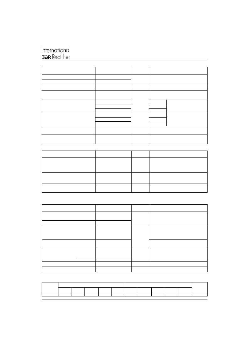
Thermal and Mechanical Specifications
Parameters
IRK.26
Units
Conditions
- 40 to 125
0.1
5
(5) Available with dv/dt = 1000V/
μ
s, to complete code add S90 i.e. IRKT26/16AS90.
°C
K/W
Nm
Mounting surface flat, smooth and greased
I
RRM
I
DRM
Max. peak reverse and
off-state leakage current
at V
RRM
, V
DRM
15
mA
T
J
= 125
o
C, gate open circuit
V
INS
RMS isolation voltage
2500 (1 min)
V
50 Hz, circuit to base, all terminals
3500 (1 sec)
shorted
dv/dt Max. critical rate of rise
500
V/
μ
s
T
J
= 125
o
C, linear to 0.67 V
DRM
,
Triggering
Blocking
P
GM
P
G(AV)
Max. average gate power
I
GM
-V
GM
gate voltage
Max. peak gate power
10
2.5
Max. peak gate current
Max. peak negative
2.5
A
4.0
2.5
1.7
270
150
80
T
J
= - 40°C
T
J
= 25°C
T
J
= 125°C
T
J
= - 40°C
T
J
= 25°C
T
J
= 125°C
T
= 125
o
C,
rated V
DRM
applied
T
= 125
o
C,
rated V
DRM
applied
mA
V
GD
Max. gate voltage
that will not trigger
Max. gate current
that will not trigger
I
GD
0.25
V
6
mA
Anode supply = 6V
resistive load
V
GT
Max. gate voltage
required to trigger
Anode supply = 6V
resistive load
I
GT
Max. gate current
required to trigger
W
V
10
Parameters
IRK. 26
Units
Conditions
Parameters
IRK. 26
Units
Conditions
A mounting compound is recommended
and the torque should be rechecked after
a period of 3 hours to allow for the
spread of the compound
Sine half wave conduction
Rect. wave conduction
Devices
Units
180
o
0.23
120
o
0.27
90
o
0.34
60
o
0.48
30
o
0.73
180
o
0.17
120
o
0.28
90
o
0.36
60
o
0.49
30
o
0.73
IRK.26
°C/W
R Conduction (per Junction)
(The following table shows the increment of thermal resistance R
thJC
when devices operate at different conduction angles than DC)
相關(guān)PDF資料 |
PDF描述 |
|---|---|
| IRK.41 | THYRISTOR/ DIODE and THYRISTOR/ THYRISTOR |
| IRK.56 | THYRISTOR/ DIODE and THYRISTOR/ THYRISTOR |
| IRK41 | THYRISTOR/ DIODE and THYRISTOR/ THYRISTOR |
| IRK430 | SUPER MAGN-A-PAK⑩ Power Modules |
| IRKD320-04 | IC LOGIC 3383 10-BIT BUS EXCHANGE SWITCH 5V -40+85C QSOP-24 55/TUBE |
相關(guān)代理商/技術(shù)參數(shù) |
參數(shù)描述 |
|---|---|
| IRK270-04 | 制造商:TRSYS 制造商全稱:Transys Electronics 功能描述:Power Module 270 Amp |
| IRK270-08 | 制造商:TRSYS 制造商全稱:Transys Electronics 功能描述:Power Module 270 Amp |
| IRK270-12 | 制造商:TRSYS 制造商全稱:Transys Electronics 功能描述:Power Module 270 Amp |
| IRK270-14 | 制造商:TRSYS 制造商全稱:Transys Electronics 功能描述:Power Module 270 Amp |
| IRK270-16 | 制造商:TRSYS 制造商全稱:Transys Electronics 功能描述:Power Module 270 Amp |
發(fā)布緊急采購,3分鐘左右您將得到回復(fù)。