- 您現(xiàn)在的位置:買賣IC網(wǎng) > PDF目錄299203 > IHLP-5050CE-060.68UH+/-20%ERE3 (VISHAY DALE) 1 ELEMENT, 0.68 uH, GENERAL PURPOSE INDUCTOR, SMD PDF資料下載
參數(shù)資料
| 型號(hào): | IHLP-5050CE-060.68UH+/-20%ERE3 |
| 廠商: | VISHAY DALE |
| 元件分類: | 通用定值電感 |
| 英文描述: | 1 ELEMENT, 0.68 uH, GENERAL PURPOSE INDUCTOR, SMD |
| 文件頁數(shù): | 1/3頁 |
| 文件大小: | 128K |
For technical questions, contact Magnetics@vishay.com
www.vishay.com
15
IHLP-5050CE-06
Vishay Dale
Document Number 34165
Revision 03-Nov-04
10% DCR Tolerance,
Low Profile, Power Inductor
FEATURES
Lowest height (3.5mm) in this package footprint.
Shielded construction.
Frequency range up to 5.0MHz.
Lowest DCR/H, in this package size.
Handles high transient current spikes without saturation.
Ultra low buzz noise, due to composite construction.
100% Lead (Pb)-free and RoHS compliant.
NOTES:
1. All test data is referenced to 25°C ambient.
2. Operating Temperature Range - 55°C to + 125°C
3. DC current (A) that will cause an approximate T of 40°C.
4. DC current (A) that will cause Lo to drop approximately 20%
5. The part temperature (ambient + temp rise) should not exceed
125°C under worst case operating conditions. Circuit design,
component placement, PWB trace size and thickness, airflow
and other cooling provisions all affect the part temperature. Part
temperature should be verified in the end application.
APPLICATIONS
Tolerance DCR for current sense applications.
Improved current balance in phased power supplies.
Improved thermal management.
PDA/Notebook/Desktop/Server and Battery powered devices.
High current, Low profile POL converters.
DC/DC converters in distributed power systems.
DC/DC converter for Field Programmable Gate Arrays.
Manufactured under one or more of the following:
US Patents; 6,198,375 / 6,204,744 / 6,449,829 / 6,460,244.
Several foreign patents, and other patents pending.
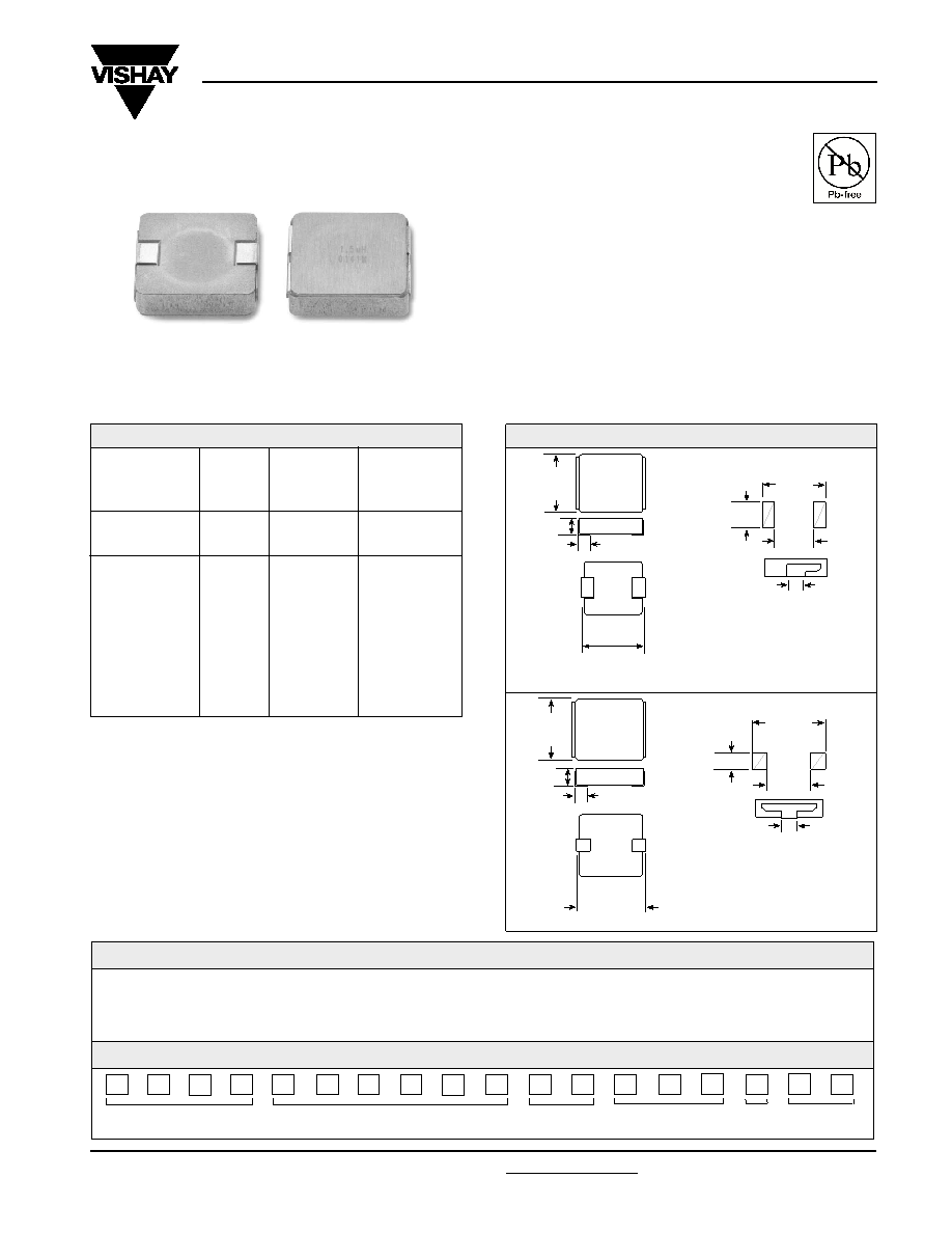
DIMENSIONS in inches [millimeters]
The diagram above applies to values 0.6H and below.
The diagram above applies to values 0.68H and above.
Typical Pad Layout
0.138
[3.5] Max.
0.520
± 0.015
[13.2
± 0.38] Max.
0.542
[13.76]
0.310
[7.87]
0.195
[4.95]
0.185
± 0.01
[4.7
± 0.3]
0.508
[12.9]
Max.
[2.3
± 0.3]
0.091
± 0.01
0.508
[12.9]
Max.
0.520
± 0.015
[13.2
± 0.38]
0.542
[13.8]
0.318
[8.1]
0.118
± 0.01
[3.0
± 0.3]
0.087
± 0.01
[2.2
± 0.254]
0.138
[3.5] Max.
0.128 [3.3]
Typical Pad Layout
GLOBAL PART NUMBER
MODEL
SIZE
INDUCTANCE
VALUE
PACKAGE
CODE
SERIES
IH
L
P
5
0
5
0
C
E
R
1
R
0M
0
6
INDUCTANCE
TOLERANCE
DESCRIPTION
IHLP-5050CE-06
1.0H
± 20%
ER
e3
MODEL
INDUCTANCE
PACKAGE
JDEC LEAD FREE
VALUE
TOLERANCE
CODE
STANDARD
STANDARD ELECTRICAL SPECIFICATIONS
Lo
DCR m
HEAT RATING
SATURATION
INDUCTANCE
±10%
CURRENT
H ± 20%
@ 25
°C
DC AMPS3
DC AMPS4
@100KHz, .25V, 0A
TYPICAL
0.60
1.85
29
51
0.68
2.34
28
49
1.0
3.21
24
40
1.5
4.97
19
35
2.2
7.20
16
29
3.3
10.69
12
27
4.7
14.27
10
24
5.6
18.19
9.5
19
10
30.86
7
14
相關(guān)PDF資料 |
PDF描述 |
|---|---|
| IHLP-5050CE-074.7UH+/-20%ERE3 | 1 ELEMENT, 4.7 uH, GENERAL PURPOSE INDUCTOR, SMD |
| IHLP-5050CE-071UH+/-20%ERE3 | 1 ELEMENT, 1 uH, GENERAL PURPOSE INDUCTOR, SMD |
| IHLP-5050CE-0710UH+/-20%ERE3 | 1 ELEMENT, 10 uH, GENERAL PURPOSE INDUCTOR, SMD |
| IHLP-5050CE-070.6UH+/-20%ERE3 | 1 ELEMENT, 0.6 uH, GENERAL PURPOSE INDUCTOR, SMD |
| IHLP-5050FD-016.8+/-20%ERE3 | 1 ELEMENT, 6.8 uH, GENERAL PURPOSE INDUCTOR, SMD |
相關(guān)代理商/技術(shù)參數(shù) |
參數(shù)描述 |
|---|---|
| IHLP-5050CE-07 | 制造商:VISHAY 制造商全稱:Vishay Siliconix 功能描述:5 % DCR Tolerance, Low Profile, Power Inductor |
| IHLP5050CEEB100M06 | 制造商:Vishay Dale 功能描述:- Bulk |
| IHLP5050CEEB100M07 | 制造商:Vishay Dale 功能描述:IND PWR SHLD 10UH 20% 100KHZ 5050 - Bulk |
| IHLP5050CEEB1R0M01 | 功能描述:固定電感器 1uH 20% RoHS:否 制造商:AVX 電感:10 uH 容差:20 % 最大直流電流:1 A 最大直流電阻:0.075 Ohms 工作溫度范圍:- 40 C to + 85 C 自諧振頻率:38 MHz Q 最小值:40 尺寸:4.45 mm W x 6.6 mm L x 2.92 mm H 屏蔽:Shielded 端接類型:SMD/SMT 封裝 / 箱體:6.6 mm x 4.45 mm |
| IHLP5050CEEB1R0M06 | 制造商:Vishay Dale 功能描述:IND PWR SHLD 1UH 20% 100KHZ 5050 - Bulk |
發(fā)布緊急采購(gòu),3分鐘左右您將得到回復(fù)。