- 您現(xiàn)在的位置:買(mǎi)賣(mài)IC網(wǎng) > PDF目錄1923 > ID82C86H (Intersil)IC TRANSCEIVER OCT BUS 20-DIP PDF資料下載
參數(shù)資料
| 型號(hào): | ID82C86H |
| 廠商: | Intersil |
| 文件頁(yè)數(shù): | 4/6頁(yè) |
| 文件大?。?/td> | 0K |
| 描述: | IC TRANSCEIVER OCT BUS 20-DIP |
| 標(biāo)準(zhǔn)包裝: | 19 |
| 類(lèi)型: | 收發(fā)器 |
| 驅(qū)動(dòng)器/接收器數(shù): | 8/8 |
| 電源電壓: | 4.5 V ~ 5.5 V |
| 安裝類(lèi)型: | 通孔 |
| 封裝/外殼: | 20-CDIP(0.300",7.62mm) |
| 供應(yīng)商設(shè)備封裝: | 20-CDIP |
| 包裝: | 管件 |

4
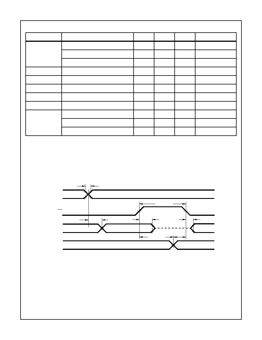
Timing Waveform
AC Electrical Specifications V
CC = 5.0V ± 10%; Freq = 1MHz: TA = -40
oC to +85oC
SYMBOL
PARAMETER
MIN
MAX
UNITS
TEST CONDITIONS
(1)
TIVOV
Input to Output Delay
Notes 1, 2
Inverting
5
30
ns
Non-Inverting
5
32
ns
(2)
TEHTV
Transmit/Receive Hold Time
5
-
ns
Notes 1, 2
(3)
TTVEL
Transmit/Receive Setup Time
10
-
ns
Notes 1, 2
(4)
TEHOZ
Output Disable Time
5
30
ns
Notes 1, 2
(5)
TELOV
Output Enable Time
10
50
ns
Notes 1, 2
(6)
TR, TF
Input Rise/Fall Times
-
20
ns
Notes 1, 2
(7)
TEHEL
Minimum Output Enable High Time
Note 3
82C86H
30
-
ns
82C86H-5
35
-
ns
NOTES:
1. All AC parameters tested as per test circuits and definitions in timing waveforms and test load circuits. Input rise and fall times are driven
at 1ns/V.
2. Input test signals must switch between VIL - 0.4V and VIH +0.4V.
3. A system limitation only when changing direction. Not a measured parameter.
NOTE: All timing measurements are made at 1.5V unless otherwise noted.
INPUTS
TR, TF (6)
2.0V
0.8V
VOH -0.1V
TELOV (5)
VOL +0.1V
TTVEL (3)
3.0V
0.45V
OUTPUTS
T
TEHEL (7)
TIVOV
(1)
TEHOZ
(4)
TEHTV (2)
OE
82C86H
相關(guān)PDF資料 |
PDF描述 |
|---|---|
| IDT5V5201DCGI | TXRX 1CH M-LVDS TO LVTTL 8-SOIC |
| IDT5V5206DCGI | TXRX 1CH M-LVDS TO LVTTL 8-SOIC |
| IDT72T6360L7-5BBI | IC FLOW-CTRL 48BIT 7-5NS 324-BGA |
| IDT72V51256L7-5BBI | IC FLOW CTRL MULTI QUEUE 256-BGA |
| IDT72V51453L7-5BBI | IC FLOW CTRL MULTI QUEUE 256-BGA |
相關(guān)代理商/技術(shù)參數(shù) |
參數(shù)描述 |
|---|---|
| ID82C86H/+ | 制造商:未知廠家 制造商全稱:未知廠家 功能描述:Single 8-bit Bus Transceiver |
| ID82C86H-5 | 制造商:INTERSIL 制造商全稱:Intersil Corporation 功能描述:CMOS Octal Bus Transceiver |
| ID82C87H | 制造商:INTERSIL 制造商全稱:Intersil Corporation 功能描述:CMOS Octal Inverting Bus Transceiver |
| ID82C87H/+ | 制造商:未知廠家 制造商全稱:未知廠家 功能描述:Single 8-Bit Inverting Bus Transceiver |
| ID82C87H-5 | 制造商:INTERSIL 制造商全稱:Intersil Corporation 功能描述:CMOS Octal Inverting Bus Transceiver |
發(fā)布緊急采購(gòu),3分鐘左右您將得到回復(fù)。