- 您現(xiàn)在的位置:買賣IC網(wǎng) > PDF目錄360707 > IC_SS PDF資料下載
參數(shù)資料
| 型號(hào): | IC_SS |
| 文件頁(yè)數(shù): | 5/36頁(yè) |
| 文件大小: | 480K |
| 代理商: | IC_SS |
第1頁(yè)第2頁(yè)第3頁(yè)第4頁(yè)當(dāng)前第5頁(yè)第6頁(yè)第7頁(yè)第8頁(yè)第9頁(yè)第10頁(yè)第11頁(yè)第12頁(yè)第13頁(yè)第14頁(yè)第15頁(yè)第16頁(yè)第17頁(yè)第18頁(yè)第19頁(yè)第20頁(yè)第21頁(yè)第22頁(yè)第23頁(yè)第24頁(yè)第25頁(yè)第26頁(yè)第27頁(yè)第28頁(yè)第29頁(yè)第30頁(yè)第31頁(yè)第32頁(yè)第33頁(yè)第34頁(yè)第35頁(yè)第36頁(yè)
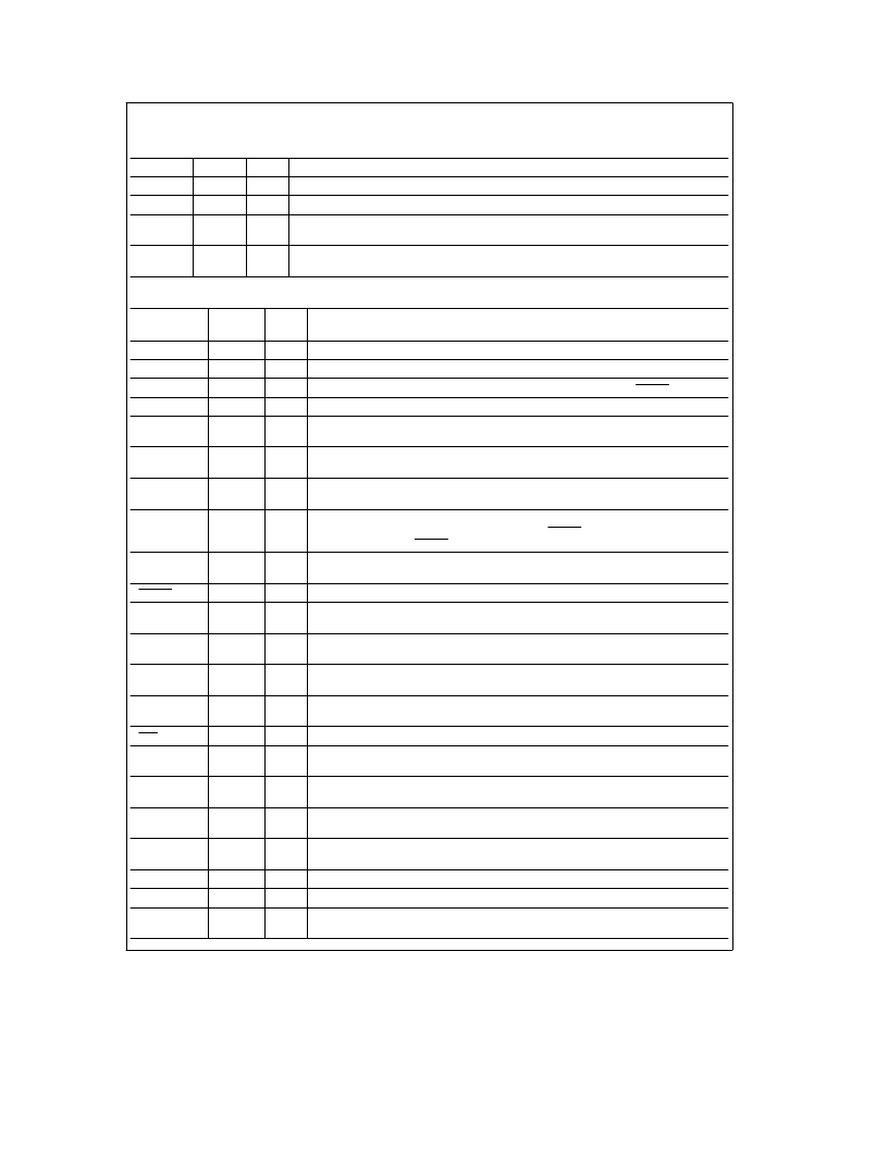
Pin Descriptions
(Continued)
TABLE I. ICSS1001 Pin Descriptions
(Continued)
Pin Name
Pin No.
Type
Function
G0
25
I
LRCD CLK recovered clock from demodulated data input from digital ASlC
G1
26
No connection
G2
27
I
LRCD recovered data from demodulated data input from digital ASIC, after Manchester
decoding
G3
28
O
WDT firmware outputs a square wave to digital chip, maintaining a one-shot. If WDT output
stops, digital ASIC will force a system reset on pin 24.
TABLE II. ICSS1002 Pin Descriptions
Pin Name
Pin No.
(V Pkg.)
Type
Function
IHICLK
1
O
Output Test Point:
A test point.
QHICLK
2
O
Output Test Point:
A test point.
8 MHz
3
O
8 MHz Output:
This is the CLK divided by 2. This output goes low while RESET is LOW.
SI
5
T
MICROWIRE Serial Input:
This pin drives the MICROWIRE SI Input on the controller.
SK
6
T
MICROWIRE Shift Clock:
This pin accepts the MICROWIRE shift clock to the Controller
interface on the IC/SS digital ASIC.
SO
7
T
MICROWIRE Serial Output:
This pin accepts the MICROWIRE serial data to the
Controller interface on the IC/SS digital ASIC.
LRCD
8
O
Recovered Data:
This is the serial data received from the power line after Manchester
decoding.
WDT
9
T
WATCHDOG
TM
Timer Disable:
This input from the controller keeps the digital ASIC
active. If it goes away, the digital ASlC will generate RESET pulse after the WATCHDOG
timers times out. This RESET pulse will reset the entire PLC chip set.
LRCDCLK
10
O
Recovered Clock:
This is the clock received from the power line after Manchester
decoding.
RESET
11
I
Reset:
Active LOW reset for the entire IC/SS chip set.
STROBE
13
T
MICROWIRE Strobe input:
This pin accepts the MICROWIRE strobe to the controller
interface on the IC/SS digital ASIC.
CSD2–CSD0
14–16
T
Controller Interface Mode Select:
These inputs are used to select the operation modes
of the controller interface circuitry on the IC/SS digital ASIC.
MTP0–MTP3
18–21
O
Test Points:
These output pins provide access to one of the filter outputs on the detector
integration bus.
LTXD
23
O
Serial Data to be transmitted:
This input is the serial data to be transmitted. It is not
Manchester encoded.
PTT
24
T
Push to talk:
This is an active low signal that puts the digital ASIC into the transmit mode.
LTXD CLK
25
T
Serial Data Transmit Clock:
This input is the clock for the serial data (LTXD) that is used
to Manchester encode the data prior to transmission.
RAW DATA
26
O
Raw Data:
This output is the raw data received by the IC/SS circuit after de-multiplex prior
to Manchester decode.
TxRDY
27
O
Transmit Data Ready:
When this signal is HIGH the parallel port is ready to accept a new
byte from the user data bus.
RxRDY
28
O
Receive Data Ready:
When this signal is HIGH there is a byte available in the parallel
port to be read by the user data bus.
LPCLK
29
O
LPCLK:
This is an internal test point.
BPCLK
30
O
BPCLK:
This is an internal test point.
CS2
31
O
Chip Select:
This is the MICROWIRE chip select output. It is used to enable read/write of
external MICROWIRE data ports.
5
相關(guān)PDF資料 |
PDF描述 |
|---|---|
| IC41C16100A-50K | 1M x 16 (16-MBIT) DYNAMIC RAM WITH EDO PAGE MODE |
| IC41C16100A-50T | 1M x 16 (16-MBIT) DYNAMIC RAM WITH EDO PAGE MODE |
| IC41C16100A-60K | 1M x 16 (16-MBIT) DYNAMIC RAM WITH EDO PAGE MODE |
| IC41C16100A-60T | 1M x 16 (16-MBIT) DYNAMIC RAM WITH EDO PAGE MODE |
| IC41C16100AS | 1M x 16 (16-MBIT) DYNAMIC RAM WITH EDO PAGE MODE |
相關(guān)代理商/技術(shù)參數(shù) |
參數(shù)描述 |
|---|---|
| ICSS1001WM | 制造商:未知廠家 制造商全稱:未知廠家 功能描述:LAN Node Controller |
| ICSS1002V4 | 制造商:未知廠家 制造商全稱:未知廠家 功能描述:Communications Interface |
| ICSS1002VJE | 制造商:未知廠家 制造商全稱:未知廠家 功能描述:Communications Interface |
| ICSS-1YR | 制造商:Black Box Corporation 功能描述:ICOMPEL S SERIES 1 YEAR ADDITIONAL WARRANTY |
| ICSS-2U-PU-N | 制造商:Black Box Corporation 功能描述:iCOMPEL S Series 2U Publisher |
發(fā)布緊急采購(gòu),3分鐘左右您將得到回復(fù)。