- 您現(xiàn)在的位置:買賣IC網(wǎng) > PDF目錄371919 > HZZ00101 Cassette Style Mating Connectors PDF資料下載
參數(shù)資料
| 型號(hào): | HZZ00101 |
| 英文描述: | Cassette Style Mating Connectors |
| 中文描述: | 卡式風(fēng)格交配器 |
| 文件頁數(shù): | 1/9頁 |
| 文件大?。?/td> | 267K |
| 代理商: | HZZ00101 |
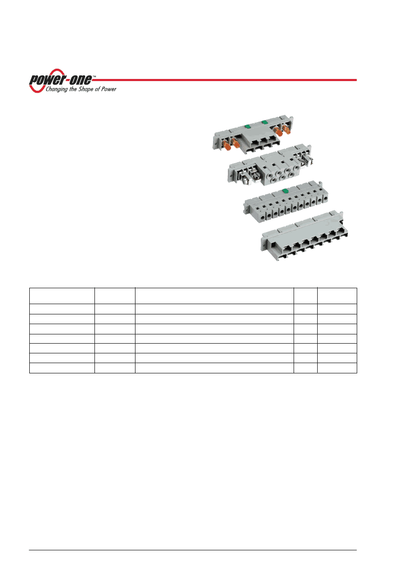
Accessories
Cassette Style Mating Connectors H11, H15, H15S2, H15S4
SEP 29, 2003 revised to MAY 24, 2006
Page 1 of 9
www.power-one.com
Table 1: H11 Connector Survey
Female connector
type
Reference
Description of terminals
Fig.
Integrated
coding
STV-H11-F/CO
HZZ00101
Faston terminals 6.3
×
0.8 mm
Faston terminals 6.3
×
0.8 mm, solderable (short moulding)
Screw terminals, 90°, 2.5 mm
2
(AWG 13), torque
≤
26.6 Ncm
Solder pin 5.2 mm,
1.6 mm
Solder pin 4.3 mm,
1.0 mm
Press fit 6.5 mm,
1.0 mm
Solder pin 5.2 mm,
1.6 mm, gold-plated contacts
2
yes
STV-H11-FS/CO
2
HZZ00104
3
yes
STV-H11-FSR/CO
HZZ00102
4
yes
STV-H11-FB/CO
1
HZZ00103
5
yes
STV-H11-FBER/CO
2
HZZ00113
5
yes
STV-H11-FP/CO
2
HZZ00111
5
yes
STV-H11-FBG/CO
2
HZZ00199
5
yes
1
See also matching Flexi-PCB for PCB-mounting of converters (See the Power-One WEB site
Accessories/ Mounting Supports
)
2
Ask Power-One for availability
Description
All 19" cassette type converters are equipped with either
H11-, H15-, H15S2 or H15S4 male connectors. Mating
female connectors are available as accessories according
to the following tables. The four H-type connector versions
are specially designed for power supply applications,
capable of handling high operating currents. The con-
nectors have an integrated code key system allowing many
coding possibilities. Converters with high output current
normally use two contacts in parallel to keep the voltage
drop across the connector as low as possible. In case of
very high currents, the connectors are fitted with round high
current contacts.
H11 Connectors
This connector has eleven contacts in one vertical column
marked 2 to 32. Mating and mounting conditions are
according to DIN 41612. The connector contacts are hard-
silver-plated and correspond to quality class 1, with respect
to electrical and mechanical life time.
This connector type (male version) is used in the following
converter series (case size):
H (H02), M (M02), and PSL (L04).
Description ....................................................................... 1
H11 Connectors ............................................................... 1
H15 Connectors ............................................................... 3
H15S2, H15S4 Connectors.............................................. 5
Technical Data.................................................................. 7
Code Key System ............................................................ 7
Connector Retention Brackets CRB................................. 8
Extraction Tool for High Current Contacts ........................ 8
Connector Retention Clips V............................................ 8
Cable Hood ...................................................................... 9
Cable Hood Retention Brackets CHRB............................ 9
Table of Contents
Page
Page
相關(guān)PDF資料 |
PDF描述 |
|---|---|
| R-AT0 | HEAD ROLLER LEVER |
| R1110N251A | LC filter, low pass, SMT, RoHS |
| R1110N251B | NOT RoHS. LC filter, low pass, SMT |
| R1110N261A | NOT RoHS. LC filter, low pass, SMT |
| R1110N261B | THREE-TERMINAL POSITIVE FIXED VOLTAGE REGULATORS |
相關(guān)代理商/技術(shù)參數(shù) |
參數(shù)描述 |
|---|---|
| HZZ00101G | 制造商:Power-One 功能描述: |
| HZZ00101-G | 功能描述:CONNECTOR FAST ON TERM 制造商:bel power solutions 系列:- 零件狀態(tài):有效 配件類型:Faston 端子 配套使用產(chǎn)品/相關(guān)產(chǎn)品:盒式轉(zhuǎn)換器 標(biāo)準(zhǔn)包裝:10 |
| HZZ00102 | 制造商:Power-One 功能描述:Conn DIN 41612 F 11 POS 7.62mm Screw ST Panel Mount |
| HZZ00102-G | 制造商:Power-One 功能描述: |
| HZZ00103-G | 功能描述:CONNECTOR PCB MOUNT 制造商:bel power solutions 系列:- 零件狀態(tài):有效 配件類型:焊接引腳端子 配套使用產(chǎn)品/相關(guān)產(chǎn)品:盒式轉(zhuǎn)換器 標(biāo)準(zhǔn)包裝:10 |
發(fā)布緊急采購,3分鐘左右您將得到回復(fù)。