- 您現(xiàn)在的位置:買賣IC網(wǎng) > PDF目錄385429 > HY5PS1G831F (Hynix Semiconductor Inc.) 1Gb DDR2 SDRAM PDF資料下載
參數(shù)資料
| 型號: | HY5PS1G831F |
| 廠商: | Hynix Semiconductor Inc. |
| 英文描述: | 1Gb DDR2 SDRAM |
| 中文描述: | 1G DDR2內(nèi)存 |
| 文件頁數(shù): | 4/33頁 |
| 文件大小: | 540K |
| 代理商: | HY5PS1G831F |
第1頁第2頁第3頁當前第4頁第5頁第6頁第7頁第8頁第9頁第10頁第11頁第12頁第13頁第14頁第15頁第16頁第17頁第18頁第19頁第20頁第21頁第22頁第23頁第24頁第25頁第26頁第27頁第28頁第29頁第30頁第31頁第32頁第33頁

Rev. 1.2 / Dec 2006
4
1
HY5PS1G431(L)F
1
HY5PS1G831(L)F
1.1 Device Features & Ordering Information
1.1.1 Key Features
VDD=1.8V
VDDQ=1.8V +/- 0.1V
All inputs and outputs are compatible with SSTL_18 interface
Fully differential clock inputs (CK, /CK) operation
Double data rate interface
Source synchronous-data transaction aligned to bidirectional data strobe (DQS, DQS)
Differential Data Strobe (DQS, DQS)
Data outputs on DQS, DQS edges when read (edged DQ)
Data inputs on DQS centers when write(centered DQ)
On chip DLL align DQ, DQS and DQS transition with CK transition
DM mask write data-in at the both rising and falling edges of the data strobe
All addresses and control inputs except data, data strobes and data masks latched on the rising
edges of the clock
Programmable CAS latency 3, 4, 5 and 6 supported
Programmable additive latency 0, 1, 2, 3, 4 and 5 supported
Programmable burst length 4/8 with both nibble sequential and interleave mode
Internal eight bank operations with single pulsed RAS
Auto refresh and self refresh supported
tRAS lockout supported
8K refresh cycles /64ms
JEDEC standard 68ball FBGA(x4/x8)
Full strength driver option controlled by EMRS
On Die Termination supported
Off Chip Driver Impedance Adjustment supported
Read Data Strobe suupported (x8 only)
Self-Refresh High Temperature Entry
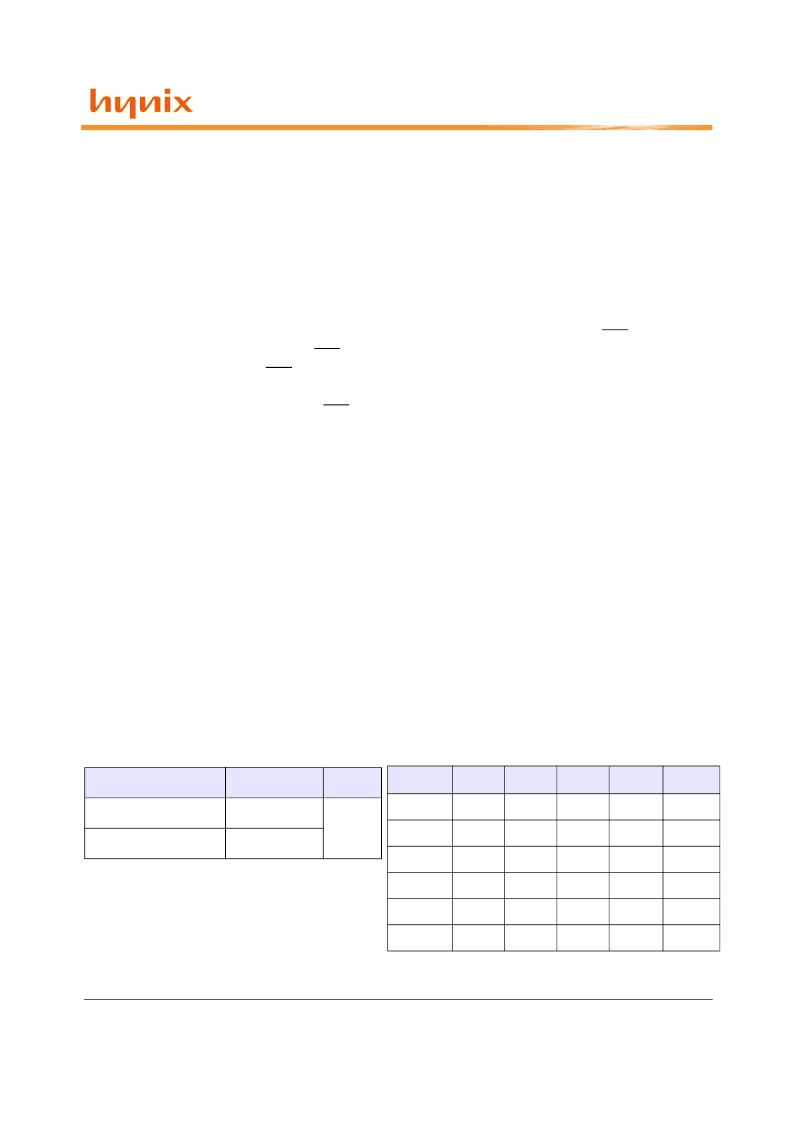
Ordering Information
Part No.
Configuration
Package
HY5PS1G431(L)F-X*
256Mx4
68Ball
HY5PS1G831(L)F-X*
128Mx8
Operating Frequency
Grade
tCK(ns)
CL
tRCD
tRP
Unit
-E3
5
3
3
3
Clk
-E4
5
4
4
4
Clk
-C4
3.75
4
4
4
Clk
-C5
3.75
5
5
5
Clk
-Y5
3
5
5
5
Clk
-Y6
3
6
6
6
Clk
Note:
-X* is the speed bin, refer to the Operation
Frequency table for complete Part No.
1. Description
相關PDF資料 |
PDF描述 |
|---|---|
| HY5PS1G831F-C4 | 1Gb DDR2 SDRAM |
| HY5PS1G831F-C5 | 1Gb DDR2 SDRAM |
| HY5PS1G831F-E3 | 1Gb DDR2 SDRAM |
| HY5PS1G831F-E4 | 1Gb DDR2 SDRAM |
| HY5PS1G831F-Y5 | 1Gb DDR2 SDRAM |
相關代理商/技術參數(shù) |
參數(shù)描述 |
|---|---|
| HY5PS1G831F-C4 | 制造商:HYNIX 制造商全稱:Hynix Semiconductor 功能描述:1Gb DDR2 SDRAM |
| HY5PS1G831F-C5 | 制造商:HYNIX 制造商全稱:Hynix Semiconductor 功能描述:1Gb DDR2 SDRAM |
| HY5PS1G831F-E3 | 制造商:HYNIX 制造商全稱:Hynix Semiconductor 功能描述:1Gb DDR2 SDRAM |
| HY5PS1G831F-E4 | 制造商:HYNIX 制造商全稱:Hynix Semiconductor 功能描述:1Gb DDR2 SDRAM |
| HY5PS1G831F-Y5 | 制造商:HYNIX 制造商全稱:Hynix Semiconductor 功能描述:1Gb DDR2 SDRAM |
發(fā)布緊急采購,3分鐘左右您將得到回復。