- 您現(xiàn)在的位置:買賣IC網(wǎng) > PDF目錄371883 > HR122-2815 Analog IC PDF資料下載
參數(shù)資料
| 型號(hào): | HR122-2815 |
| 英文描述: | Analog IC |
| 中文描述: | 模擬IC |
| 文件頁數(shù): | 3/6頁 |
| 文件大?。?/td> | 90K |
| 代理商: | HR122-2815 |
HR12 2 - 28 12
Base Model
Input Voltage
Output Voltage
Number of Outputs
B4-49
HR120 SERIES
12 WATT
DC/DC C
ONVERTERS
DUAL OUTPUT MODELS
PARAMETER
HR122-2812
TYP
HR122-2815
TYP
CONDITION
MIN
MAX
MIN
MAX
UNITS
OUTPUT VOLTAGE
+V
OUT
– V
OUT
11.88
12.0
12.12
14.85
15.0
15.15
VDC
11.82
12.0
12.18
14.77
15.0
15.23
OUTPUT CURRENT
1, 2
OUTPUT POWER
2
—
0.5
1.0
—
0.4
0.8
A
+V
OUT
– V
OUT
TOTAL
—
—
10.8
—
—
10.8
—
—
10.8
—
—
10.8
W
—
—
12
—
—
12
OUTPUT RIPPLE
VOLTAGE
10 kHz TO 2 MHz
—
30
60
—
30
60
mV p-p
LINE REGULATION
+V
OUT
– V
OUT
+V
OUT
– V
OUT
—
5
50
—
5
50
mV
MIN. TO MAX. V
IN
LOAD REGULATION
—
30
150
—
30
150
—
5
50
—
10
50
mV
NO LOAD TO FULL
—
30
150
—
30
150
CROSS REGULATION
20% TO 80% LOAD
3
50% LOAD
4
—
5
10
—
4
8
%
—
4
5
—
3
5
INPUT VOLTAGE
CONTINUOUS
16
28
40
19
28
40
VDC
TRANSIENT 50 ms
—
—
50
—
—
50
INPUT CURRENT
NO LOAD
FULL LOAD
INHIBITED
—
—
—
25
—
1.9
35
545
3
—
—
—
25
—
1.9
35
540
3
mA
INPUT RIPPLE
CURRENT
10 kHz TO 2 MHz
—
175
240
—
175
240
mA p-p
EFFICIENCY
LOAD FAULT
5
78
81
—
80
83
—
%
POWER DISSIPATION
OVERLOAD
—
—
2.8
—
—
2
W
SHORT CIRCUIT
—
—
5
—
—
5
START-UP
DELAY
—
150
250
—
150
250
ms
Notes
1. Applies to both outputs.
2. Maximum combined output power is 12 watts. A maximum of 90% is available from either output.
3. 20% to 80% load on the positive output and 80% to 20% on the negative output. See Figure 8.
4. 50% load on the positive output and 50% to 20% load on the negative output. 50% load on the negative output and
50% to 20% load on the positive output. See Figure 7.
5. Indefinite short circuit protection not guaranteed above 85°C case temperature.
Electrical Characteristics: 25°C Tc, 28 VDC Vin, 100% load, unless otherwise specified.
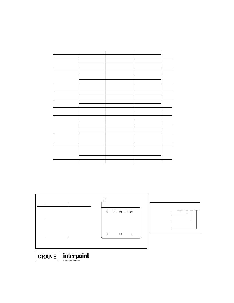
MODEL NUMBER KEY
PIN OUT
Pin
1
2
3
4
5
6
7
8
Single Output
Inhibit
No connection
Output Common
Positive Output
No connection
Case Ground
Input Common
Positive Input
Dual Output
Inhibit
Positive Output
Output Common
Negative Output
No connection
Case Ground
Input Common
Positive Input
BOTTOM VIEW
HR120
Squared corner and dot on
top of cover indicate pin one.
1
2
3
4
5
8
7
6
F
IGURE
1: P
IN
O
UT
See Section B8, case E1, for dimensions
相關(guān)PDF資料 |
PDF描述 |
|---|---|
| HR151-1205 | DC-to-DC Voltage Converter |
| HR151-1212 | DC-to-DC Voltage Converter |
| HR151-1215 | DC-to-DC Voltage Converter |
| HR151-2805 | DC-to-DC Voltage Converter |
| HR151-2812 | DC-to-DC Voltage Converter |
相關(guān)代理商/技術(shù)參數(shù) |
參數(shù)描述 |
|---|---|
| HR1224W | 制造商:CSB BATTERY OF AMERICA 功能描述:BATTERY |
| HR1224WF2 | 功能描述:密封鉛酸電池 12 VOLT RECHARG BATT RoHS:否 制造商:CSB 輸出電壓:12 V 容量: 大小: 端接類型:Faston Tab |
| HR1224WF2F1 | 功能描述:密封鉛酸電池 12V 24W .250"/.187" Tabs RoHS:否 制造商:CSB 輸出電壓:12 V 容量: 大小: 端接類型:Faston Tab |
| HR1227W | 制造商:CSB-BATTERY 制造商全稱:CSB-BATTERY 功能描述:specially designed for high efficient discharge application |
| HR1227WF2 | 功能描述:密封鉛酸電池 RoHS:否 制造商:CSB 輸出電壓:12 V 容量: 大小: 端接類型:Faston Tab |
發(fā)布緊急采購,3分鐘左右您將得到回復(fù)。