- 您現(xiàn)在的位置:買(mǎi)賣(mài)IC網(wǎng) > PDF目錄1996 > HMC830LP6GE (Hittite Microwave Corporation)IC FRACT-N PLL W/VCO 40QFN PDF資料下載
參數(shù)資料
| 型號(hào): | HMC830LP6GE |
| 廠(chǎng)商: | Hittite Microwave Corporation |
| 文件頁(yè)數(shù): | 7/14頁(yè) |
| 文件大小: | 0K |
| 描述: | IC FRACT-N PLL W/VCO 40QFN |
| 視頻文件: | HMC830LP6GE PLL with Integrated VCO |
| 標(biāo)準(zhǔn)包裝: | 1 |
| 類(lèi)型: | 整數(shù) N/小數(shù) N 分頻 |
| PLL: | 是 |
| 輸入: | CMOS |
| 輸出: | CMOS |
| 電路數(shù): | 1 |
| 比率 - 輸入:輸出: | 1:1 |
| 差分 - 輸入:輸出: | 無(wú)/是 |
| 頻率 - 最大: | 3GHz |
| 除法器/乘法器: | 是/無(wú) |
| 電源電壓: | 3.3V,5V |
| 工作溫度: | -40°C ~ 85°C |
| 安裝類(lèi)型: | 表面貼裝 |
| 封裝/外殼: | 40-VQFN 裸露焊盤(pán) |
| 供應(yīng)商設(shè)備封裝: | 40-QFN 裸露焊盤(pán)(6x6) |
| 包裝: | 標(biāo)準(zhǔn)包裝 |
| 其它名稱(chēng): | 1127-1071-6 |
第1頁(yè)第2頁(yè)第3頁(yè)第4頁(yè)第5頁(yè)第6頁(yè)當(dāng)前第7頁(yè)第8頁(yè)第9頁(yè)第10頁(yè)第11頁(yè)第12頁(yè)第13頁(yè)第14頁(yè)

For price, delivery and to place orders: Hittite Microwave Corporation, 2 Elizabeth Drive, Chelmsford, MA 01824
Phone: 978-250-3343
Fax: 978-250-3373
Order On-line at www.hittite.com
Application Support: Phone: 978-250-3343 or apps@hittite.com
P
LL
s
w
it
h
in
t
e
g
r
at
e
d
V
C
O
-
s
M
t
2
HMC830LP6GE
v03.0512
Fractional-n Pll with integrated Vco
25 - 3000 Mhz
general description
the hMC830LP6ge is a low noise, wide band, Fractional-n Phase-Locked-Loop (PLL) that features an integrated
Voltage Controlled Oscillator (VCO) with a fundamental frequency of 1500 Mhz - 3000 Mhz, and an integrated VCO
Output divider (divide by 1/2/4/6.../60/62), that together allow the hMC830LP6ge to generate frequencies from
25 Mhz to 3000 Mhz. the integrated Phase detector (Pd) and delta-sigma modulator, capable of operating at up to
100 Mhz, permit wider loop-bandwidths with excellent spectral performance.
the hMC830LP6ge features industry leading phase noise and spurious performance, across all frequencies, that
enable it to minimize blocker effects, and improve receiver sensitivity and transmitter spectral purity. the superior
noise floor (< -170 dBc/hz) makes the hMC830LP6ge an ideal source for a variety of applications - such as; LO for
rF mixers, a clock source for high-frequency data-converters, or a tunable reference source for ultra-low spurious
applications.
additional features of the hMC830LP6ge include rF output power control from 0 to 9 dB (3 dB steps), output Mute
function, and a delta-sigma modulator exact Frequency Mode which enables users to generate output frequencies
with 0 hz frequency error.
For theory of operation and register map refer to the “PLLs with integrated VCOs - rF VCOs Operating guide”. To
view the Operating Guide, please visit www.hittite.com and choose HMC830LP6GE from the “Search by Part
Number” pull down menu.
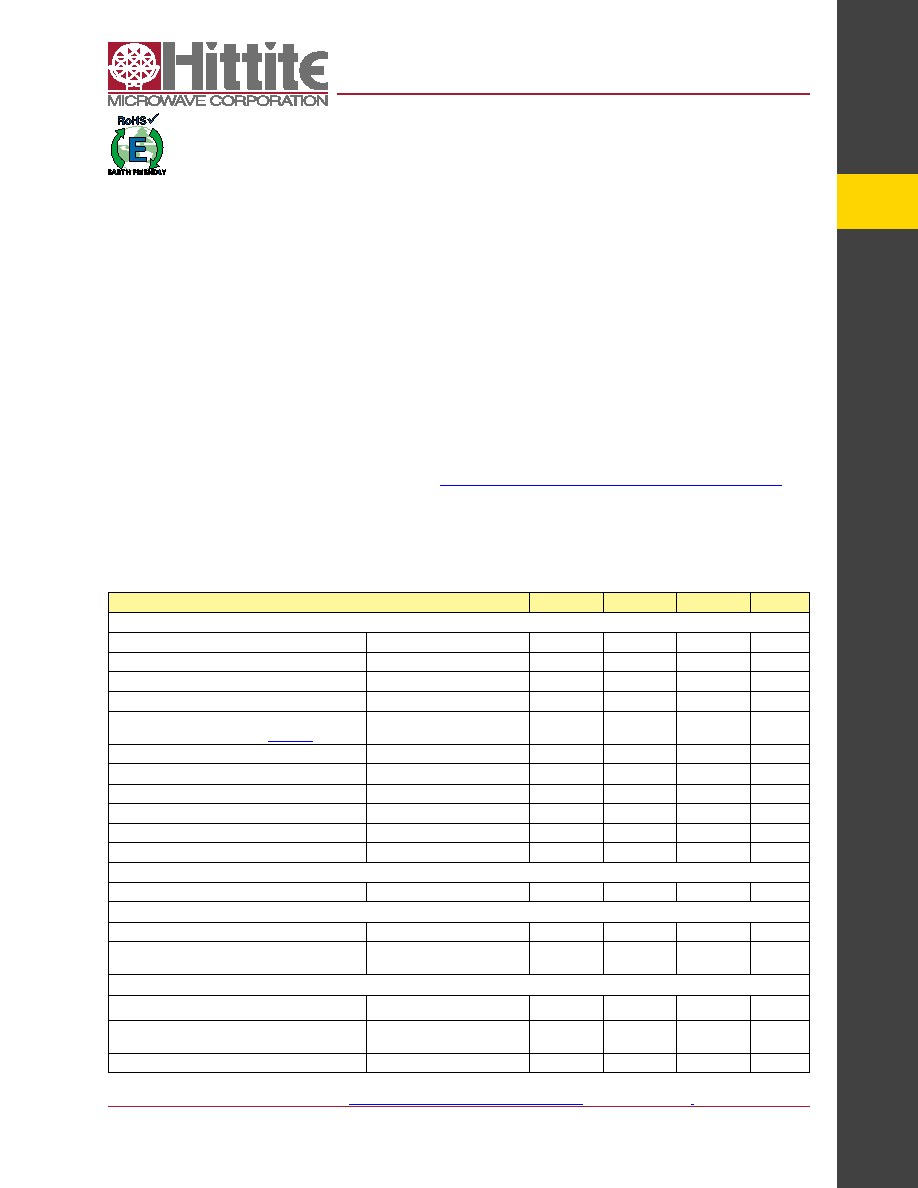
Parameter
Condition
Min.
typ.
Max.
Units
RF Output Characteristics
Output Frequency
25
3000
Mhz
VCO Frequency at PLL input
1500
3000
Mhz
rF Output Frequency at fVCO
1500
3000
Mhz
Output Power
rF Output Power at fVCO = 2000 Mhz
across all Frequencies see Figure 10
Broadband Matched internally
[1]
4.5
6
7.5
dBm
Output Power Control
3 dB steps
7
9
dB
Harmonics
fo Mode at 2 ghz
2nd / 3rd / 4th
-20/-29/-45
dBc
fo/2 Mode at 2ghz/2 = 1 ghz
2nd / 3rd / 4th
-23/-15/-35
dBc
fo/30 Mode at 3 ghz/30 = 100 Mhz
2nd / 3rd / 4th
-25/-10/-33
dBc
fo/62 Mode at 1550 Mhz/62 = 25 Mhz
2nd / 3rd / 4th
-17/-8/-21
dBc
VCO Output Divider
VCO rF divider range
1,2,4,6,8,...,62
1
62
PLL RF Divider Characteristics
19-Bit n-divider range (integer)
Max = 219 - 1
16
524,287
19-Bit n-divider range (Fractional)
Fractional nominal divide ratio
varies (-3 / +4) dynamically max
20
524,283
REF Input Characteristics
Max ref input Frequency
350
Mhz
ref input Voltage
aC Coupled
[2]
1
2
3.3
Vp-p
ref input Capacitance
5
pF
electrical Specifications
VPPcP, VddlS, Vcc1, Vcc2 = 5 V; rVdd, aVdd, dVdd3V, VccPd, VcchF, VccPS = 3.3 V
Min and Max Specified across temp -40 °c to 85 °c
[1] Measured single-ended. additional 3 dB possible with differential outputs.
[2] Measured with 100 Ω external termination. see hittite PLL w/ integraged VCOs Operating guide reference input stage section for more details.
相關(guān)PDF資料 |
PDF描述 |
|---|---|
| HMP8117CNZ | IC VIDEO DECODER NTSC/PAL 80PQFP |
| HMP8156ACNZ | IC VIDEO ENCODER NTSC/PAL 64MQFP |
| HSP45102SC-40Z | IC OSC NCO 40MHZ 28-SOIC |
| HSP45106JC-33Z | IC OSC NCO 33MHZ 84-PLCC |
| HSP45116AVC-52Z | IC OSC NCO 52MHZ 160-MQFP |
相關(guān)代理商/技術(shù)參數(shù) |
參數(shù)描述 |
|---|---|
| HMC830LP6GE_1110 | 制造商:HITTITE 制造商全稱(chēng):Hittite Microwave Corporation 功能描述:FRACTIONAL-N PLL WITH INTEGRATED VCO 25 - 3000 MHz |
| HMC830LP6GE_12 | 制造商:HITTITE 制造商全稱(chēng):Hittite Microwave Corporation 功能描述:Fractional-N PLL with Integrated VCO |
| HMC830LP6GETR | 制造商:Hittite Microwave Corp 功能描述:IC FRACT-N PLL W/VCO 40QFN |
| HMC831LP6CE | 制造商:Hittite Microwave Corp 功能描述:IC PLL W/VCO FRACTIONAL-N 40-QFN |
| HMC831LP6CE_10 | 制造商:HITTITE 制造商全稱(chēng):Hittite Microwave Corporation 功能描述:FRACTIONAL-N SYNTHESIZER WITH INTEGRATED VCO, 1815 - 2010 MHz |
發(fā)布緊急采購(gòu),3分鐘左右您將得到回復(fù)。