- 您現(xiàn)在的位置:買賣IC網(wǎng) > PDF目錄370584 > HIP5600 (Harris Corporation) Thermally Protected High Voltage Linear Regulator PDF資料下載
參數(shù)資料
| 型號: | HIP5600 |
| 廠商: | Harris Corporation |
| 英文描述: | Thermally Protected High Voltage Linear Regulator |
| 中文描述: | 熱保護的高電壓線性穩(wěn)壓器 |
| 文件頁數(shù): | 7/16頁 |
| 文件大小: | 175K |
| 代理商: | HIP5600 |
7
junction. With no heat sink C
S
equals zero and
θ
SA
equals the
difference between
θ
JA
and
θ
JC
. The following equations pre-
dict the transient junction temperature and the time to thermal
shutdown for ambient temperatures up to +85
o
C and power
levels up to 8W. The output current limit temperature coeffi-
cient (Figure 39) precludes continuous operation above 8W.
For the TO-220, C
P
is 0.9Ws to 1.1Ws per degree compared
to about 2.6mWs per degree for the integrated circuit and C
S
is 0.9Ws per degree per gram for aluminum heat sinks.
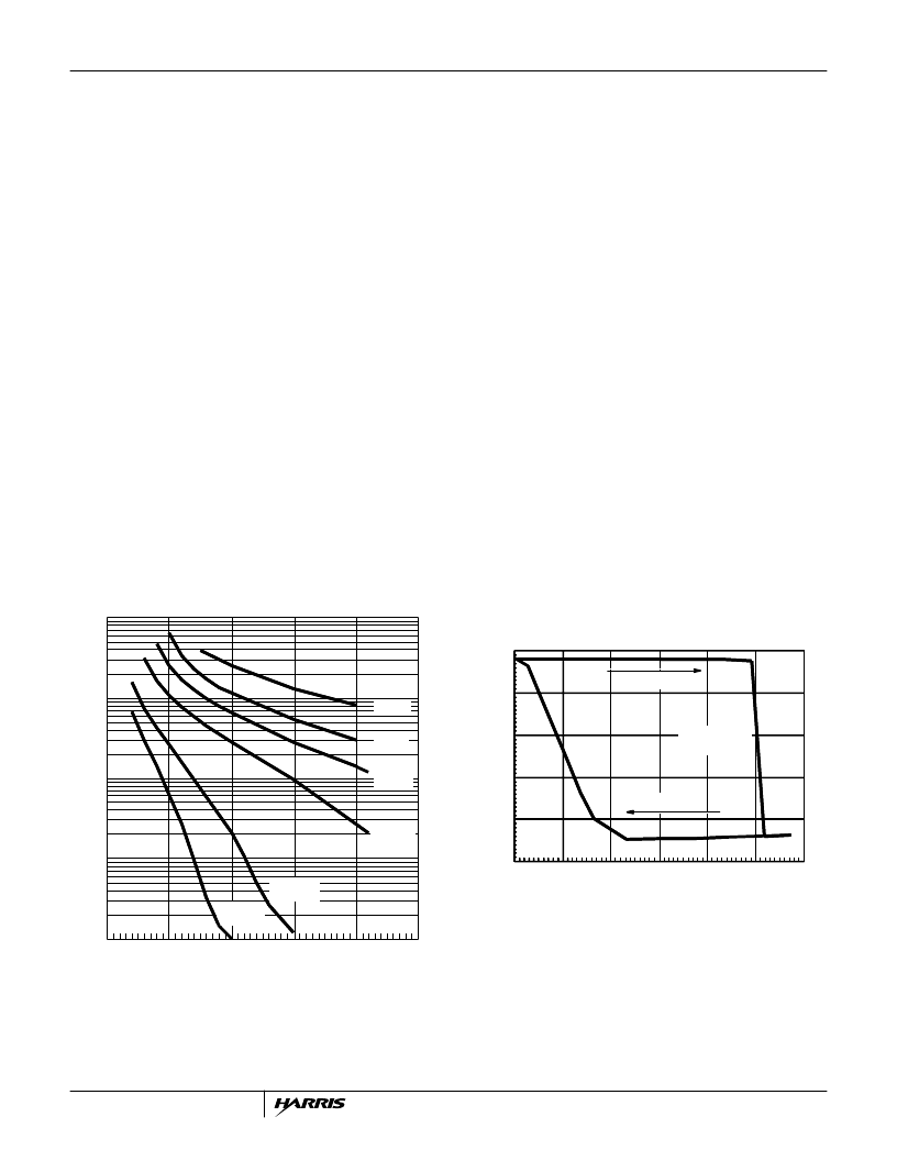
Figure 8 shows the time to thermal shutdown versus power
dissipation for a part in +22
o
C still air and at various elevated
ambient temperatures with a
θ
SA
of +27
o
C/W from forced air
flow.
For the shorter shutdown times, the
θ
SA
value is not impor-
tant but the thermal capacitances are. A more accurate
equation for the transient silicon surface temperature can be
derived from the model shown in Figure 7. Due to the distrib-
uted nature of the package thermal capacitance, the second
time constant is 1.7 times larger than expected.
FIGURE 8. TIME TO THERMAL SHUTDOWN vs POWER
DISSIPATION
Thermal Shutdown Hysteresis
Figure 9 shows the HIP5600 thermal hysteresis curve with
V
IN
= 100V
DC
, V
OUT
= 5V and I
OUT
= 10mA. Hysteresis is
added to the thermal shutdown circuit to prevent oscillations
as the junction temperature approaches the thermal shut-
down limit. The thermal shutdown is reset when the input
voltage is removed, goes negative (i.e. AC operation) or
when the part cools down.
FIGURE 9. THERMAL HYSTERESIS CURVE
AC to DC Operation
Since the HIP5600 has internal high voltage diodes in series
with its input, it can be connected directly to an AC power
line. This is an improvement over typical low current supplies
constructed from a high voltage diode and voltage dropping
resistor to bias a low voltage zener. The HIP5600 provides
better line and load regulation, better efficiency and heat
T
J
t
( )
T
A
P
θ
JC
P
θ
SA
1 e
t
–
τ
----
–
+
+
=
τ
θ
SA
C
P
C
S
+
(
)
≡
Where:
(EQ. 9)
t
τ
ln
–
P
θ
JC
-------------------------------------------------------------------
θ
SA
SA
+
(
)
T
+
T
–
=
(EQ. 10)
T
POWER DISSIPATION (W)
+22
o
C
+70
o
C
+85
o
C
+115
o
C
+120
o
C
+100
o
C
10
2
10
1
10
0
10
10
-2
0.0
2.0
4.0
6.0
8.0
10
TJt
( )
TA
T1
T2
T3
+
+
+
=
T3
0.6P
θ
JC1 e
t
–
τ
3
-------
–
≡
T2
0.4P
θ
JC1 e
t
–
τ
2
-------
–
≡
T1
P
θ
SA1 e
t
–
τ
1
-------
–
≡
τ
1
θ
SACP
CS
+
(
)
≡
τ
2
0.7
θ
JC
-----------------------------------------------------------
+
+
(
≡
τ
3
0.6
θ
JCCD
≡
(EQ. 11C)
(EQ. 11D)
Where:
Where:
Where:
(EQ. 11B)
(EQ. 11A)
CASE TEMPERATURE (
o
C)
I
O
HEATING
SHUTDOWN
REGION
COOLING
10
8.0
6.0
4.0
2.0
0.0
98.0
105.0
113.0
120
127
135
142
HIP5600
相關(guān)PDF資料 |
PDF描述 |
|---|---|
| HIP8112A | NTSC/PAL Video Decoder |
| HIR19-21C | Technical Data Sheet 0.8mm Height Flat Top Infrared LED |
| HIR19-L11 | Technical Data Sheet 0.8mm Height Flat Top Infrared LED |
| HIR204C | 3mm Infrared LED, T-1 |
| HIR | 5mm Infrared LED, T-1 3/4 |
相關(guān)代理商/技術(shù)參數(shù) |
參數(shù)描述 |
|---|---|
| HIP5600_02 | 制造商:INTERSIL 制造商全稱:Intersil Corporation 功能描述:Thermally Protected High Voltage Linear Regulator |
| HIP5600EVAL1 | 制造商:Harris Corporation 功能描述: |
| HIP5600EVAL2 | 制造商:Rochester Electronics LLC 功能描述:- Bulk |
| HIP5600EVAL3 | 制造商:Harris Corporation 功能描述: |
| HIP5600EVAL4 | 制造商:Rochester Electronics LLC 功能描述:- Bulk |
發(fā)布緊急采購,3分鐘左右您將得到回復(fù)。