- 您現(xiàn)在的位置:買賣IC網(wǎng) > PDF目錄384398 > HE83R143 (King Billion Electronics Co., Ltd.) 8-BIT MICRO-CONTROLLER PDF資料下載
參數(shù)資料
| 型號: | HE83R143 |
| 廠商: | King Billion Electronics Co., Ltd. |
| 英文描述: | 8-BIT MICRO-CONTROLLER |
| 中文描述: | 8位微控制器 |
| 文件頁數(shù): | 3/11頁 |
| 文件大小: | 306K |
| 代理商: | HE83R143 |
KING BILLION ELECTRONICS CO., LTD
駿
億
電
子
股
份
有
限
公
司
HE83R143
HE80000 SERIES
3
V1.02E
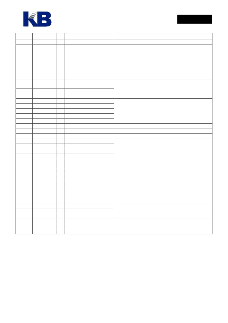
Pin#
Pin name
I/O
Function
Description
input (No tri-state structure).
Mask options
:
MO_LIO14[7..0]=1 ~ LCD Pin.
15..22
PRT14[7:0]/
SEG[63:56]
B/
O
8-pin bi-directional I/O port
that is shared with LCD
segment pin.
=0 ~ I/O Pin.
MO_14PP[7..0]=1 ~ Push-pull.
=0 ~ Open-drain.
Output must be “1” before reading whenever use them as
input (No tri-state structure).
14..7
79..86
23..
78
101
100
89
88
87
99
90
102
91
92
93
94
95
96
97
98
COM[15:0]
O LCD COMmon Output
SEG[55:0]
O LCD SEGment Output
LCD Data filled from F0H, please refer the LCD RAM
map.
L V1
L V2
L V3
L V4
L V5
LCDGS
LCDVTB
LCDVX
LC4B
LC4A
LC3B
LC3A
LC2B
LC2A
LC1B
LC1A
B LCD Bias Voltage 1
B
LCD Bias Voltage 2
B
LCD Bias Voltage 3
B
LCD Bias Voltage 4
B
LCD Bias Voltage 5
B
LCD Gain Setting Pin
B
Charge Pump Capacitor Pin Larger voltage stair than LCxA, LCxB stair
B
Charge Pump Capacitor Pin Smaller voltage stair than LCxA, LCxB stair
B
Charge Pump Capacitor Pin
B
Charge Pump Capacitor Pin
B
Charge Pump Capacitor Pin
B
Charge Pump Capacitor Pin
B
Charge Pump Capacitor Pin
B
Charge Pump Capacitor Pin
B
Charge Pump Capacitor Pin
B
Charge Pump Capacitor Pin
O The PWM output can drive
speaker or buzzer directly.
O D/A output.
Bit 1 of VOC = ‘1’ , Turn on DA
Set the bit1(DA=1) of VOC register to turn on DAC with
VO output.
I OPAMP negative input pin.
I OPAMP positive input pin.
O OPAMP output pin.
P Positive Power Input
P Power Ground Input
GND_PWM
P Dedicated PWM Ground
LV5> LV4> LV3> LV2> LV1
。
Adjust Resistor between LCDGS and LV2 to set LV5 for
LCD glass. The formula is LV5 = 2.5*LV2
。
(Bias=1/5)
Suggest that LV2=2.0V, so LV5=5.0V.
~300K between LCDGS and LV2
LV2
2.0 Volt
≒
Different LCD Bias must be matching its
Capacitor
Configuration
relatively. This IC is with all pins for
type-IV LCD Driver. Some of charge pump pins was not
using since the bias of this IC was fixed at 1/5.
5
PWM
Set the bit2 of VOC register as one to turn on PWM.
104
VO
105
DAO
O DAC Voice Output
106
107
108
115
103
6
OPIN
OPIP
OPO
VDD
GND
Built-in OP comparator.
Set Bit 0 of VOC = ‘1’ , Turn on OP
Adding 0.1 μF capacitor as by-pass capacitor on power
pins is necessary.(within 1 cm distance)
相關(guān)PDF資料 |
PDF描述 |
|---|---|
| HE83R540 | 8-BIT MICRO-CONTROLLER |
| HE84760B | 8-bit Micro-controller |
| HE84760 | 8-bit Micro-controller |
| HE84761 | 8-bit Micro-controller |
| HE847701 | 8-bit Micro-controller |
相關(guān)代理商/技術(shù)參數(shù) |
參數(shù)描述 |
|---|---|
| HE83R143(S) | 制造商:未知廠家 制造商全稱:未知廠家 功能描述: |
| HE83R540 | 制造商:KB 制造商全稱:KB 功能描述:8-BIT MICRO-CONTROLLER |
| HE83R540(S) | 制造商:未知廠家 制造商全稱:未知廠家 功能描述: |
| HE8404SG | 制造商:OPNEXT 制造商全稱:OPNEXT 功能描述:GaAlAs Infrared Emitting Diode |
| HE8404SG_06 | 制造商:OPNEXT 制造商全稱:OPNEXT 功能描述:GaAlAs Infrared Emitting Diode |
發(fā)布緊急采購,3分鐘左右您將得到回復(fù)。