- 您現(xiàn)在的位置:買賣IC網(wǎng) > PDF目錄370462 > HD40A4354H (Hitachi,Ltd.) 4-bit HMCS400-Series microcomputer PDF資料下載
參數(shù)資料
| 型號: | HD40A4354H |
| 廠商: | Hitachi,Ltd. |
| 英文描述: | 4-bit HMCS400-Series microcomputer |
| 中文描述: | 4位HMCS400系列微機 |
| 文件頁數(shù): | 62/100頁 |
| 文件大小: | 398K |
| 代理商: | HD40A4354H |
第1頁第2頁第3頁第4頁第5頁第6頁第7頁第8頁第9頁第10頁第11頁第12頁第13頁第14頁第15頁第16頁第17頁第18頁第19頁第20頁第21頁第22頁第23頁第24頁第25頁第26頁第27頁第28頁第29頁第30頁第31頁第32頁第33頁第34頁第35頁第36頁第37頁第38頁第39頁第40頁第41頁第42頁第43頁第44頁第45頁第46頁第47頁第48頁第49頁第50頁第51頁第52頁第53頁第54頁第55頁第56頁第57頁第58頁第59頁第60頁第61頁當前第62頁第63頁第64頁第65頁第66頁第67頁第68頁第69頁第70頁第71頁第72頁第73頁第74頁第75頁第76頁第77頁第78頁第79頁第80頁第81頁第82頁第83頁第84頁第85頁第86頁第87頁第88頁第89頁第90頁第91頁第92頁第93頁第94頁第95頁第96頁第97頁第98頁第99頁第100頁
HD404358 Series
62
Pin Setting:
The R0
0
/
SCK
pin is controlled by writing data to the serial mode register (SMR: $005). The
R0
1
/SI and R0
2
/SO pins are controlled by writing data to port mode register A (PMRA: $004). Refer to the
following Registers for Serial Interface section for details.
Transmit Clock Source Setting:
The transmit clock source is set by writing data to the serial mode
register (SMR: $005) and port mode register C (PMRC: $025). Refer to the following Registers for Serial
Interface section for details.
Data Setting:
Transmit data is set by writing data to the serial data register (SRL: $006, SRU, $007).
Receive data is obtained by reading the contents of the serial data register. The serial data is shifted by the
transmit clock and is input from or output to an external system.
The output level of the SO pin is invalid until the first data is output after MCU reset, or until the output
level control in idle states is performed.
Transfer Control:
The serial interface is activated by the STS instruction. The octal counter is reset to 000
by this instruction, and it increments at the rising edge of the transmit clock. When the eighth transmit
clock signal is input or when serial transmission/receive is discontinued, the octal counter is reset to 000,
the serial interrupt request flag (IFS: $003, bit 2) is set, and the transfer stops.
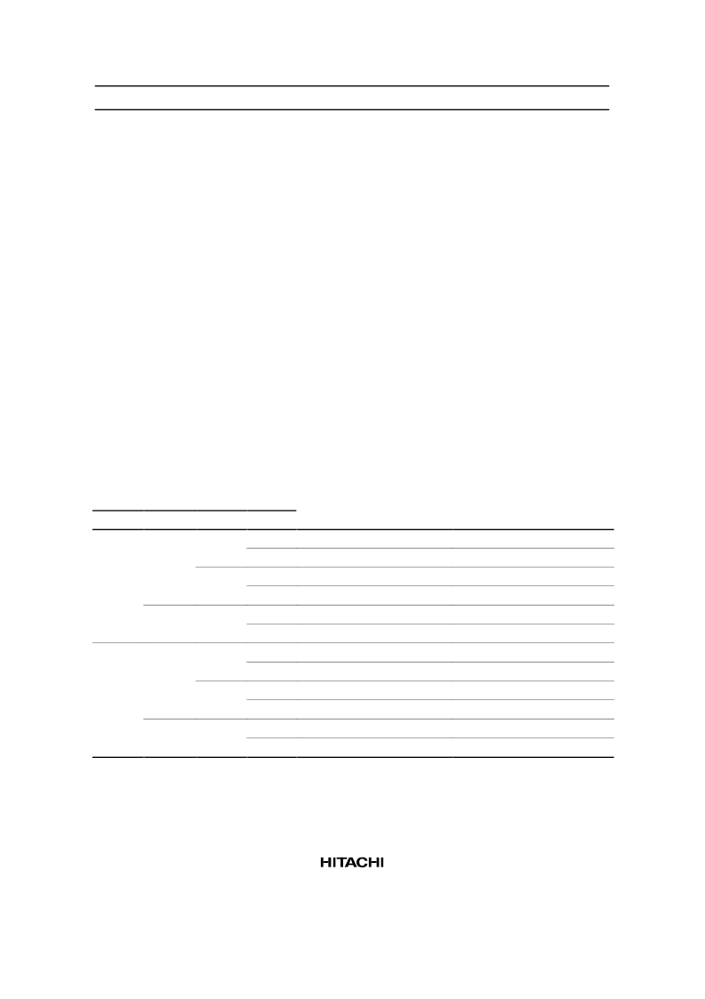
When the prescaler output is selected as the transmit clock, the transmit clock frequency is selected as 4t
cyc
to 8192t
cyc
by setting bits 0 to 2 (SMR0– SMR2) of serial mode register (SMR: $005) and bit 0 (PMRC0)
of port mode register C (PMRC: $025) as listed in table 28.
Table 28
Serial Transmit Clock (Prescaler Output)
PMRC
SMR
Bit 0
Bit 2
Bit 1
Bit 0
Prescaler Division Ratio
Transmit Clock Frequency
0
0
0
0
÷
2048
÷
512
÷
128
÷
32
÷
8
÷
2
÷
4096
÷
1024
÷
256
÷
64
÷
16
÷
4
4096t
cyc
1024t
cyc
256t
cyc
64t
cyc
16t
cyc
4t
cyc
8192t
cyc
2048t
cyc
512t
cyc
128t
cyc
32t
cyc
8t
cyc
1
1
0
1
1
0
0
1
1
0
0
0
1
1
0
1
1
0
0
1
相關(guān)PDF資料 |
PDF描述 |
|---|---|
| HD40A4354S | 4-bit HMCS400-Series microcomputer |
| HD40A4356 | 4-bit HMCS400-Series microcomputer |
| HD40A4356H | 4-bit HMCS400-Series microcomputer |
| HD40A4356S | 66 POS MOLDED PGA SOCKET |
| HD40A4358H | 4-bit HMCS400-Series microcomputer |
相關(guān)代理商/技術(shù)參數(shù) |
參數(shù)描述 |
|---|---|
| HD40A4354S | 制造商:HITACHI 制造商全稱:Hitachi Semiconductor 功能描述:4-bit HMCS400-Series microcomputer |
| HD40A4356 | 制造商:RENESAS 制造商全稱:Renesas Technology Corp 功能描述:microcomputer has an A/D converter, |
| HD40A4356H | 制造商:HITACHI 制造商全稱:Hitachi Semiconductor 功能描述:4-bit HMCS400-Series microcomputer |
| HD40A4356R | 制造商:未知廠家 制造商全稱:未知廠家 功能描述:HMCS43XXFamily User's Manual/Device |
| HD40A4356S | 制造商:HITACHI 制造商全稱:Hitachi Semiconductor 功能描述:4-bit HMCS400-Series microcomputer |
發(fā)布緊急采購,3分鐘左右您將得到回復(fù)。