- 您現(xiàn)在的位置:買(mǎi)賣(mài)IC網(wǎng) > PDF目錄370462 > HD404448 (Hitachi,Ltd.) 4-bit HMCS400-Series microcomputer(4位單片微計(jì)算機(jī)) PDF資料下載
參數(shù)資料
| 型號(hào): | HD404448 |
| 廠商: | Hitachi,Ltd. |
| 英文描述: | 4-bit HMCS400-Series microcomputer(4位單片微計(jì)算機(jī)) |
| 中文描述: | 4位HMCS400系列微機(jī)(4位單片微計(jì)算機(jī)) |
| 文件頁(yè)數(shù): | 32/123頁(yè) |
| 文件大小: | 726K |
| 代理商: | HD404448 |
第1頁(yè)第2頁(yè)第3頁(yè)第4頁(yè)第5頁(yè)第6頁(yè)第7頁(yè)第8頁(yè)第9頁(yè)第10頁(yè)第11頁(yè)第12頁(yè)第13頁(yè)第14頁(yè)第15頁(yè)第16頁(yè)第17頁(yè)第18頁(yè)第19頁(yè)第20頁(yè)第21頁(yè)第22頁(yè)第23頁(yè)第24頁(yè)第25頁(yè)第26頁(yè)第27頁(yè)第28頁(yè)第29頁(yè)第30頁(yè)第31頁(yè)當(dāng)前第32頁(yè)第33頁(yè)第34頁(yè)第35頁(yè)第36頁(yè)第37頁(yè)第38頁(yè)第39頁(yè)第40頁(yè)第41頁(yè)第42頁(yè)第43頁(yè)第44頁(yè)第45頁(yè)第46頁(yè)第47頁(yè)第48頁(yè)第49頁(yè)第50頁(yè)第51頁(yè)第52頁(yè)第53頁(yè)第54頁(yè)第55頁(yè)第56頁(yè)第57頁(yè)第58頁(yè)第59頁(yè)第60頁(yè)第61頁(yè)第62頁(yè)第63頁(yè)第64頁(yè)第65頁(yè)第66頁(yè)第67頁(yè)第68頁(yè)第69頁(yè)第70頁(yè)第71頁(yè)第72頁(yè)第73頁(yè)第74頁(yè)第75頁(yè)第76頁(yè)第77頁(yè)第78頁(yè)第79頁(yè)第80頁(yè)第81頁(yè)第82頁(yè)第83頁(yè)第84頁(yè)第85頁(yè)第86頁(yè)第87頁(yè)第88頁(yè)第89頁(yè)第90頁(yè)第91頁(yè)第92頁(yè)第93頁(yè)第94頁(yè)第95頁(yè)第96頁(yè)第97頁(yè)第98頁(yè)第99頁(yè)第100頁(yè)第101頁(yè)第102頁(yè)第103頁(yè)第104頁(yè)第105頁(yè)第106頁(yè)第107頁(yè)第108頁(yè)第109頁(yè)第110頁(yè)第111頁(yè)第112頁(yè)第113頁(yè)第114頁(yè)第115頁(yè)第116頁(yè)第117頁(yè)第118頁(yè)第119頁(yè)第120頁(yè)第121頁(yè)第122頁(yè)第123頁(yè)
HD404449 Series
32
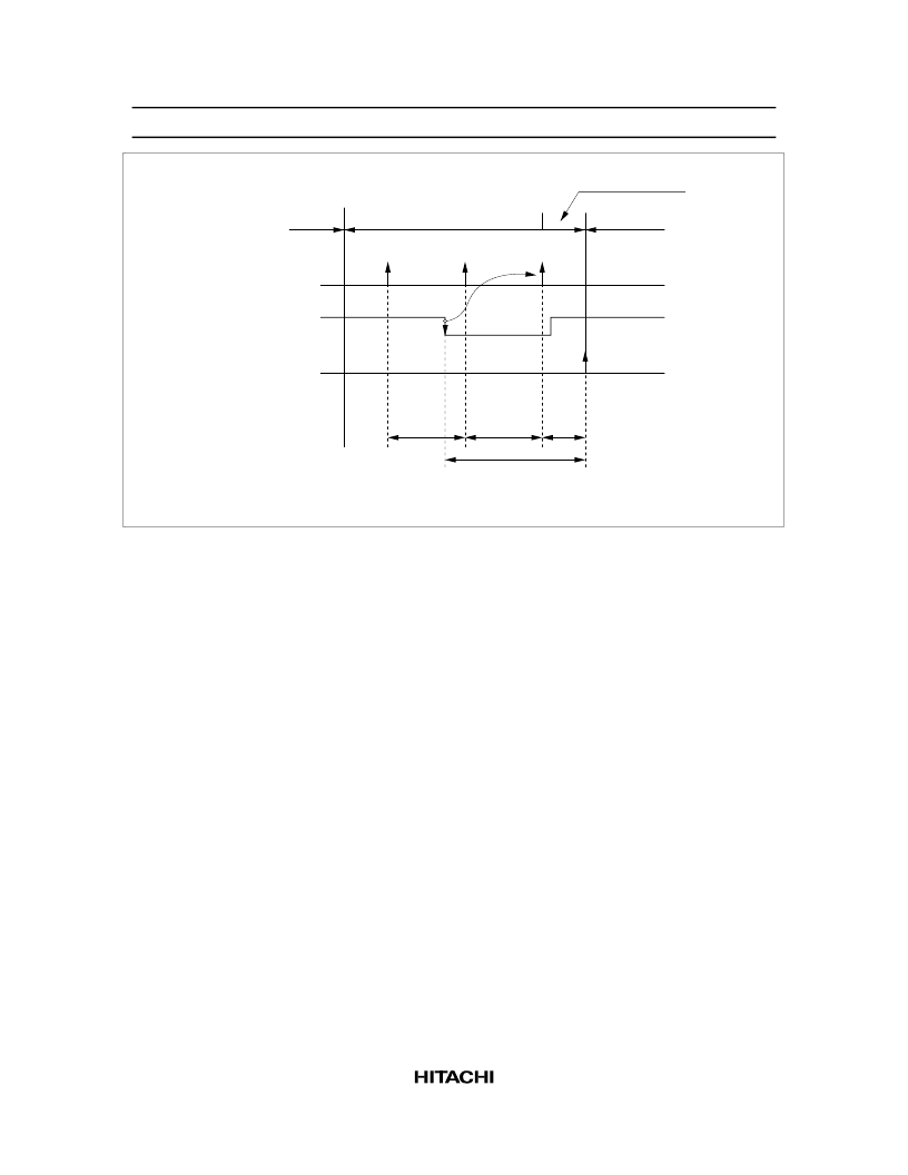
Active mode
Watch mode
Active mode
Oscillation
stabilization period
Interrupt strobe
INT
Interrupt request
generation
(During the transition
from watch mode to
active mode only)
0
T
T
t
RC
Tx
T:
t :
Interrupt frame length
Oscillation stabilization period
Figure 17 Interrupt Frame
Subactive Mode:
The OSC
1
and OSC
2
oscillator stops and the MCU operates with a clock generated by
the X1 and X2 oscillator. In this mode, functions other than A/D conversion operate. However, because
the operating clock is slow, the power dissipation becomes low, next to watch mode.
The CPU instruction execution speed can be selected as 244
μ
s or 122
μ
s by setting bit 2 (SSR2) of the
system clock select register (SSR: $029). Note that the SSR2 value must be changed in active mode. If the
value is changed in subactive mode, the MCU may malfunction.
When the STOP or SBY instruction is executed in subactive mode, the MCU enters either watch or active
mode, depending on the statuses of the low speed on flag (LSON: $020, bit 0) and the direct transfer on
flag (DTON: $020, bit 3).
Subactive mode is an optional function that the user must specify on the function option list.
Interrupt Frame:
In watch and subactive modes,
CLK
is applied to timer A and the
INT
0
circuit. Prescaler
W and timer A operate as the time-base and generate the timing clock for the interrupt frame. Three
interrupt frame lengths (T) can be selected by setting the miscellaneous register (MIS: $00C) (figure 18).
In watch and subactive modes, the timer-A/
INT
0
interrupt is generated synchronously with the interrupt
frame. The interrupt request is generated synchronously with the interrupt strobe timing except during
transition to active mode. The falling edge of the
INT
0
signal is input asynchronously with the interrupt
frame timing, but it is regarded as input synchronously with the second interrupt strobe clock after the
falling edge. An overflow and interrupt request in timer A is generated synchronously with the interrupt
strobe timing.
相關(guān)PDF資料 |
PDF描述 |
|---|---|
| HD404449 | 4-bit HMCS400-Series microcomputer(4位單片微計(jì)算機(jī)) |
| HD4074459 | 4-bit HMCS400-Series microcomputer(4位單片微計(jì)算機(jī)) |
| HD404458 | 4-bit HMCS400-Series microcomputer(4位單片微計(jì)算機(jī)) |
| HD404459 | 4-bit HMCS400-Series microcomputer(4位單片微計(jì)算機(jī)) |
| HD40A4052 | 4-Bit Single-Chip Microcomputer(4位單片微計(jì)算機(jī)) |
相關(guān)代理商/技術(shù)參數(shù) |
參數(shù)描述 |
|---|---|
| HD404448H | 制造商:HITACHI 制造商全稱(chēng):Hitachi Semiconductor 功能描述:HD404449 SERIES |
| HD404448TF | 制造商:HITACHI 制造商全稱(chēng):Hitachi Semiconductor 功能描述:HD404449 SERIES |
| HD404449 | 制造商:HITACHI 制造商全稱(chēng):Hitachi Semiconductor 功能描述:HD404449 SERIES |
| HD404449H | 制造商:HITACHI 制造商全稱(chēng):Hitachi Semiconductor 功能描述:HD404449 SERIES |
| HD404449SERIES | 制造商:未知廠家 制造商全稱(chēng):未知廠家 功能描述: |
發(fā)布緊急采購(gòu),3分鐘左右您將得到回復(fù)。