- 您現(xiàn)在的位置:買賣IC網(wǎng) > PDF目錄370458 > HD404369H (Hitachi,Ltd.) 4-bit HMCS400-Series microcomputer PDF資料下載
參數(shù)資料
| 型號: | HD404369H |
| 廠商: | Hitachi,Ltd. |
| 英文描述: | 4-bit HMCS400-Series microcomputer |
| 中文描述: | 4位HMCS400系列微機 |
| 文件頁數(shù): | 77/115頁 |
| 文件大小: | 452K |
| 代理商: | HD404369H |
第1頁第2頁第3頁第4頁第5頁第6頁第7頁第8頁第9頁第10頁第11頁第12頁第13頁第14頁第15頁第16頁第17頁第18頁第19頁第20頁第21頁第22頁第23頁第24頁第25頁第26頁第27頁第28頁第29頁第30頁第31頁第32頁第33頁第34頁第35頁第36頁第37頁第38頁第39頁第40頁第41頁第42頁第43頁第44頁第45頁第46頁第47頁第48頁第49頁第50頁第51頁第52頁第53頁第54頁第55頁第56頁第57頁第58頁第59頁第60頁第61頁第62頁第63頁第64頁第65頁第66頁第67頁第68頁第69頁第70頁第71頁第72頁第73頁第74頁第75頁第76頁當前第77頁第78頁第79頁第80頁第81頁第82頁第83頁第84頁第85頁第86頁第87頁第88頁第89頁第90頁第91頁第92頁第93頁第94頁第95頁第96頁第97頁第98頁第99頁第100頁第101頁第102頁第103頁第104頁第105頁第106頁第107頁第108頁第109頁第110頁第111頁第112頁第113頁第114頁第115頁
HD404369 Series
77
If more than eight transmit clocks are input in transfer state, at the eighth clock including a spurious pulse
by noise, the octal counter reaches 000, the serial interrupt request flag (IFS: $003, bit 2) is set, and
transmit clock wait state is entered. At the falling edge of the next normal clock signal, the transfer state is
entered. After the transfer completion processing is performed and IFS is reset, writing to the serial mode
register (SMR: $005) changes the state from transfer to STS wait. At this time IFS is set again, and
therefore the error can be detected.
Notes on Use:
Initialization after writing to registers: If port mode register A (PMRA: $004) is written to in transmit
clock wait state or in transfer state, the serial interface must be initialized by writing to the serial mode
register (SMR: $005) again.
Serial interrupt request flag (IFS: $003, bit 2) set: If the state is changed from transfer to another by
writing to the serial mode register (SMR: $005) or executing the STS instruction during the first low
pulse of the transmit clock, the serial interrupt request flag is not set. To set the serial interrupt request
flag, serial mode register write or STS instruction execution must be programmed to be executed after
confirming that the
SCK
pin is at 1, that is, after executing the input instruction to port R0.
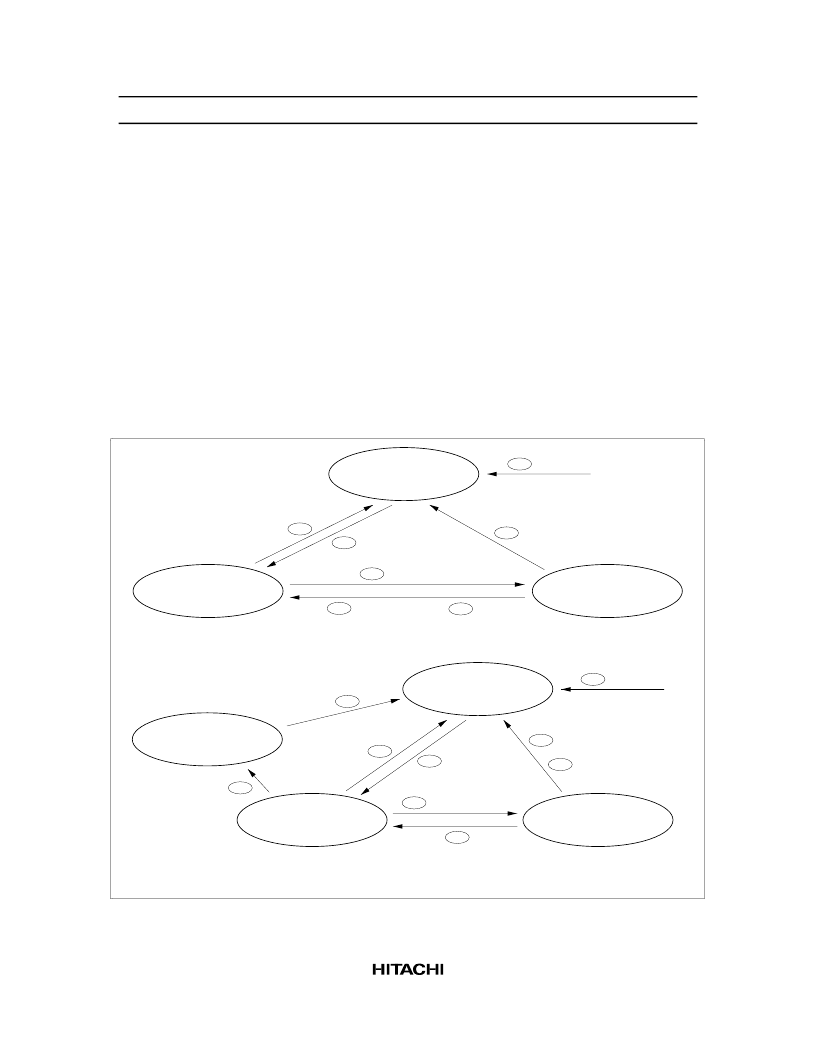
STS wait state
(octal counter = 000,
transmit clock disabled)
Transmit clock wait state
(octal counter = 000)
Transfer state
(octal counter
≠
000)
MCU reset
00
SMR write
04
STS instruction
01
Transmit clock
02
8 transmit clocks
03
STS instruction (IFS 1)
05
SMR write (IFS 1)
06
External clock mode
STS wait state
(octal counter = 000,
transmit clock disabled)
Transmit clock wait state
(octal counter = 000)
Transfer state
(octal counter
≠
000)
SMR write
14
STS instruction
11
Transmit clock
12
15
STS instruction (IFS 1)
8 transmit clocks
13
Internal clock mode
Continuous clock output state
(PMRA 0, 1 = 0, 0)
SMR write
18
Transmit clock 17
16
Note: Refer to the Operating States section for the corresponding encircled numbers.
MCU reset
10
SMR write (IFS 1)
Figure 59 Serial Interface State Transitions
相關(guān)PDF資料 |
PDF描述 |
|---|---|
| HD404369S | 4-bit HMCS400-Series microcomputer |
| HD404369F | 4-bit HMCS400-Series microcomputer |
| HD404372 | Low-Voltage AS Microcomputers with On-Chip A/D Converter(帶片上A/D轉(zhuǎn)換器的低壓微計算機) |
| HD404082 | Low-Voltage AS Microcomputers with On-Chip A/D Converter(帶片上A/D轉(zhuǎn)換器的低壓微計算機) |
| HD404084 | Low-Voltage AS Microcomputers with On-Chip A/D Converter(帶片上A/D轉(zhuǎn)換器的低壓微計算機) |
相關(guān)代理商/技術(shù)參數(shù) |
參數(shù)描述 |
|---|---|
| HD404369S | 制造商:HITACHI 制造商全稱:Hitachi Semiconductor 功能描述:4-bit HMCS400-Series microcomputer |
| HD404369SERIES | 制造商:未知廠家 制造商全稱:未知廠家 功能描述: |
| HD404372 | 制造商:未知廠家 制造商全稱:未知廠家 功能描述:HMCS43XXFamily User's Manual/Device |
| HD404372FT | 制造商:未知廠家 制造商全稱:未知廠家 功能描述:4-Bit Microcontroller |
| HD404372H | 制造商:RENESAS 制造商全稱:Renesas Technology Corp 功能描述:Low-Voltage AS Microcomputers with On-Chip A/D Converter |
發(fā)布緊急采購,3分鐘左右您將得到回復(fù)。