- 您現(xiàn)在的位置:買賣IC網(wǎng) > PDF目錄371788 > HD1-15531 ENCODER/DECODER|CMOS|DIP|40PIN|CERAMIC PDF資料下載
參數(shù)資料
| 型號(hào): | HD1-15531 |
| 英文描述: | ENCODER/DECODER|CMOS|DIP|40PIN|CERAMIC |
| 中文描述: | 編碼/解碼器|的CMOS |雙酯| 40PIN |陶瓷 |
| 文件頁數(shù): | 3/16頁 |
| 文件大小: | 278K |
| 代理商: | HD1-15531 |
3
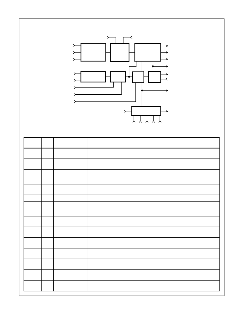
DECODER
Pin Description
PIN
NUMBER
TYPE
NAME
SECTION
DESCRIPTION
1
V
CC
Both
Positive supply pin. A 0.1
μ
F decoupling capacitor from V
CC
(pin 1) to GROUND
(pin 21) is recommended.
2
O
VALID WORD
Decoder
Output high indicates receipt of a valid word, (valid parity and no Manchester
errors).
3
O
TAKE DATA’
Decoder
A continuous, free running signal provided for host timing or data handling. When
data is present on the bus, this signal will be synchronized to the incoming data
and will be identical to TAKE DATA.
4
O
TAKE DATA
Decoder
Output is high during receipt of data after identification of a valid sync pulse and
two valid Manchester bits.
5
O
SERIAL DATA OUT
Decoder
Delivers received data in correct NRZ format.
6
I
SYNCHRONOUS
DATA
Decoder
Input presents Manchester data directly to character identification logic.
SYNCHRONOUS DATA SELECT must be held high to use this input. If not
used, this pin must be held high.
7
I
SYNCHRONOUS
DATA SELECT
Decoder
In high state allows the synchronous data to enter the character identification
logic. Tie this input low for asynchronous data.
8
I
SYNCHRONOUS
CLOCK
Decoder
Input provides externally synchronized clock to the decoder, for use when re-
ceiving synchronous data. This input must be tied high when not in use.
9
I
DECODER CLOCK
Decoder
Input drives the transition finder, and the synchronizer which in turn supplies the
clock to the balance of the decoder. Input a frequency equal to 12X the data rate.
10
I
SYNCHRONOUS
CLOCK SELCT
Decoder
In high state directs the SYNCHRONOUS CLOCK to control the decoder char-
acter identification logic. A low state selects the DECODER CLOCK.
11
I
BIPOLAR ZERO IN
Decoder
A high input should be applied when the bus is in its negative state. This pin must
be held high when the unipolar input is used.
12
I
BIPOLAR ONE IN
Decoder
A high input should be applied when the bus is in its positive state. This pin must
he held low when the unipolar input is used.
13
I
UNIPOLAR DATA IN
Decoder
With pin 11 high and pin 12 low, this pin enters unipolar data into the transition
finder circuit. If not used this input must be held low.
BIPOLAR
ONE IN
BIPOLAR
ONE IN
DECODER
MASTER
RESET
13
12
11
9
15
SYNCHRONIZER
8
10
22
DECODER
CLK SELECT
SYNCHRONOUS
SYNCHRONOUS
CLK SELECT
DECODER
SHIFT CLK
VALID WORD
PARITY
SELECT
SERIAL
DATA OUT
TAKE DATA
COMMAND SYNC
DATA SYNC
4
17
5
2
16
19
DECODER
RESET
14
3
TAKE DATA’
20 40
23
36
39
BIT
COUNTER
CLOCK
SELECT
DATA
7
8
SYNCHRONOUS
DATA SELECT
SYNCHRONOUS
DATA
C
0
C
1
C
2
C
3
C
4
TRANSITION
FINDER
DATA
SELECT
GATE
PARITY
CHECK
CHARACTER
IDENTIFIER
BIT
RATE
CLK
UNIPOLAR
DATA IN
CLK
CLK
HD-15531
相關(guān)PDF資料 |
PDF描述 |
|---|---|
| HD1-15531B-2 | Encoder/Decoder |
| HD1-6402B-9 | CMOS Universal Asynchronous Receiver Transmitter (UART) |
| HD1-6402R-9 | CMOS Universal Asynchronous Receiver Transmitter (UART) |
| HD3-6402B-9 | CMOS Universal Asynchronous Receiver Transmitter (UART) |
| HD3-6402R-9 | CMOS Universal Asynchronous Receiver Transmitter (UART) |
相關(guān)代理商/技術(shù)參數(shù) |
參數(shù)描述 |
|---|---|
| HD1-15531/883 | 制造商:INTERSIL 制造商全稱:Intersil Corporation 功能描述:CMOS Manchester Encoder-Decoder |
| HD1-15531-2 | 制造商:未知廠家 制造商全稱:未知廠家 功能描述:Logic IC |
| HD1-15531-8 | 制造商:INTERSIL 制造商全稱:Intersil Corporation 功能描述:CMOS Manchester Encoder-Decoder |
| HD1-15531-9 | 制造商:Rochester Electronics LLC 功能描述:- Bulk |
| HD1-15531B | 制造商:INTERSIL 制造商全稱:Intersil Corporation 功能描述:CMOS Manchester Encoder-Decoder |
發(fā)布緊急采購,3分鐘左右您將得到回復(fù)。