- 您現(xiàn)在的位置:買賣IC網(wǎng) > PDF目錄371775 > HC55171IM (INTERSIL CORP) 5 REN Ringing SLIC for ISDN Modem/TA and WLL PDF資料下載
參數(shù)資料
| 型號: | HC55171IM |
| 廠商: | INTERSIL CORP |
| 元件分類: | 模擬傳輸電路 |
| 英文描述: | 5 REN Ringing SLIC for ISDN Modem/TA and WLL |
| 中文描述: | TELECOM-SLIC, PQCC28 |
| 封裝: | PLASTIC, MS-018AB, LCC-28 |
| 文件頁數(shù): | 10/18頁 |
| 文件大小: | 153K |
| 代理商: | HC55171IM |
71
feedback circuitry becomes relatively easy to match the
impedance at points “A” and “B”.
Impedance Matching Design Equations
Matching the impedance of the SLIC to the load is
accomplished by writing a loop equation starting at V
D
and
going around the loop to V
C
.
The loop equation to match the impedance of any load is as
follows (note: V
RX
= 0 for this analysis):
R
RF
Equation 22 can be separated into two terms, the feedback
(-8R
S
(R
Z0
/R
RF
)) and the loop impedance (+4R
S
+R
L
).
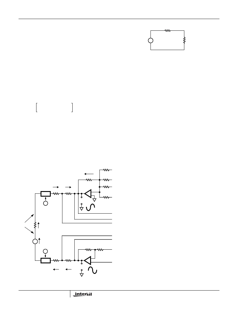
The result is shown in Equation 23. Figure 8 is a schematic
representation of Equation 18. To match the impedance of
the SLIC to the impedance of the load, set:
If R
RF
is made to equal 8R
S
then:
Therefore to match the HC5517, with R
S
equal to 50
, to a
600
load:
and
To prevent loading of the V
TX
output, the value of R
Z0
and
R
RF
are typically scaled by a factor of 100:
Since the impedance matching is a function of the voltage
gain, scaling of the resistors to achieve a standard value is
recommended.
For complex impedances the above analysis is the same.
Refer to application note AN9607 (“Impedance Matching
Design Equations for the HC5509 Series of SLICs”) for the
values of KR
RF
and KR
Z0
for many worldwide typical line
impedances.
Through SLIC Ringing
The HC55171 uses linear amplification to produce the ringing
signal. As a result the ringing SLIC can produce sinusoid,
trapezoid or square wave ringing signals. Regardless of the
wave shape, the ringing signal is balanced. The balanced
waveform is another way of saying that the tip and ring DC
potentials are the same during ringing. The following figure
shows the Tip and Ring waveforms for sinusoid and trapezoid
wave shapes as can be displayed using an oscilloscope.
Pertinent Bellcore Ringing Specifications
Bellcore has defined bounds around the existing unbalanced
ringing signal that is supplied by the central office. The
R
R
L
I
L
+
-
I
L
+
-
I
L
+
-
I
L
+
-
I
L
+
-
R
P1
= R
P2
= R
S1
= R
S2
= R
S
I
R
V
TR
V
IN
VC
4
–
RS
=
VD
4RS
=
I
L
+
-
TIP
B
A
IR
4
–
-----------------------------
(
)
R
RF
------------
------------
+
=
FIGURE 7. AC VOLTAGE GAI
-
+
+
-
V
C
V
D
R
S2
R
P2
R
P1
R
S1
90k
90k
R
R/2
+
-
R
+
-
RING
+
R/20
4R
S
I
L
–
-----------
2R
S
I
L
V
IN
–
R
L
I
L
2R
S
I
L
4R
S
I
L
–
R
RF
-----------
+
+
+
(EQ. 20)
V
IN
8R
S
I
L
–
R
RF
-----------
4R
S
I
L
R
L
I
L
+
+
=
(EQ. 21)
V
IN
I
L
8R
S
–
R
RF
-----------
4R
S
R
L
+
+
=
(EQ. 22)
V
IN
I
L
------------
8
–
R
S
R
RF
-----------
4R
S
R
L
+
[
]
+
=
(EQ. 23)
V
IN
R
L
8RS
R
RF
------------
4RS
+
LOAD
SLIC
FIGURE 8. SCHEMATIC REPRESENTATION OF EQUATION 20
+
8R
S
R
RF
-----------
4R
S
R
L
=
+
(EQ. 24)
R
Z0
4R
S
R
L
=
+
(EQ. 25)
R
RF
8R
S
8 50
)
400
=
=
=
(EQ. 26)
R
Z0
R
L
4
–
R
S
600
200
–
400
=
=
=
(EQ. 27)
KR
Z0
40k
=
KR
RF
40k
=
(EQ. 28)
KR
RF
40k
=
(
)
KR
Z0
100 Resistive
200
–
)
--------------------------
+
=
(EQ. 29)
HC55171
相關PDF資料 |
PDF描述 |
|---|---|
| HC55185BIM | VoIP Ringing SLIC Family |
| HC55185CIM | VoIP Ringing SLIC Family |
| HC55183ECM | Extended Reach Ringing SLIC Family |
| HC55180DIM | Extended Reach Ringing SLIC Family |
| HC55181AIM | Wirewound Resistors, type NH Non-Inductive Winding |
相關代理商/技術參數(shù) |
參數(shù)描述 |
|---|---|
| HC5517B | 制造商:INTERSIL 制造商全稱:Intersil Corporation 功能描述:Low Cost 3 REN Ringing SLIC for ISDN Modem/TA and WL |
| HC5517B WAF | 制造商:Harris Corporation 功能描述: |
| HC5517BCB | 制造商:Rochester Electronics LLC 功能描述:- Bulk 制造商:Harris Corporation 功能描述: |
| HC5517BCB96S2495 | 制造商:Rochester Electronics LLC 功能描述:- Bulk |
| HC5517BCM | 制造商:Rochester Electronics LLC 功能描述:- Bulk |
發(fā)布緊急采購,3分鐘左右您將得到回復。