- 您現(xiàn)在的位置:買賣IC網(wǎng) > PDF目錄385344 > GS9020ACTVE3 (Gennum Corporation) GENLINX -TM II GS9020A Serial Digital Video Input Processor PDF資料下載
參數(shù)資料
| 型號: | GS9020ACTVE3 |
| 廠商: | Gennum Corporation |
| 英文描述: | GENLINX -TM II GS9020A Serial Digital Video Input Processor |
| 中文描述: | GENLINX -商標二GS9020A串行數(shù)字視頻輸入處理器 |
| 文件頁數(shù): | 5/31頁 |
| 文件大小: | 258K |
| 代理商: | GS9020ACTVE3 |
第1頁第2頁第3頁第4頁當前第5頁第6頁第7頁第8頁第9頁第10頁第11頁第12頁第13頁第14頁第15頁第16頁第17頁第18頁第19頁第20頁第21頁第22頁第23頁第24頁第25頁第26頁第27頁第28頁第29頁第30頁第31頁

19922 - 3
5 of 31
G
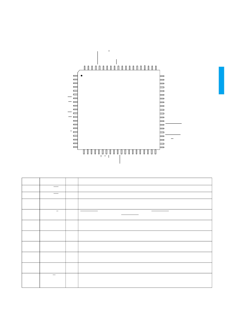
PIN CONNECTIONS
PIN DESCRIPTIONS
NUMBER
SYMBOL
TYPE
DESCRIPTION
6, 7
SDI, SDI
I
Differential serial data inputs.
10, 11
SCI, SCI
I
Differential serial clock inputs.
15
HOSTIF_MODE
I
Host interface mode select. When HIGH, the host interface is configured for I2C mode. When
LOW, the host interface is configured for parallel port mode.
16
FIFOE/S
I
FIFO_RESET pulse control. When HIGH, the output FIFO_RESET pulse occurs on the EAV
word. When LOW, the output FIFO_RESET pulse occurs on the SAV word.
17
CRC_MODE
I
CRC_MODE enable. When HIGH, CRC_MODE is enabled. When LOW, CRC_MODE is
disabled.
18 - 20
P[7:5]
I/O
In parallel port mode, these are bits 7:5 of the host interface address/data bus. In I2C mode,
these pins must be set LOW.
21
SCL/P4
I/O
In parallel port mode, this is bit 4 of the host interface address/data bus. In I2C mode, this is the
serial clock input for the I2C port.
22
SDA/P3
I/O
In parallel port mode, this is bit 3 of the host interface address/data bus. In I2C mode, this is the
serial data pin for the I2C port.
23 - 25
A[2:0]/P[2:0]
I/O
In parallel port mode, these are bits 2:0 of the host interface address/data bus. In I2C mode,
these are input bits which define the I2C slave address for the device.
26
R/W
I
Parallel port read/write control. When HIGH, the parallel port is configured as an output (read
mode). When LOW, the parallel port is configured as an input (write mode). In I2C mode, this
pin must be set HIGH.
VDD
GND
GND
VDD
VDD
SDI
SDI
SDI
VDD
SDI
VDD
SCI
SCI
SCI
VDD
SCI
VDD
GND
HOSTIF_MODE
FIFOE/S
CRC_MODE
P7
P6
P5
DOUT9
DOUT8
DOUT7
DOUT6
DOUT5
DOUT4
DOUT3
DOUT2
DOUT1
VDD
GND
DOUT0
PCLKOUT
FIFO_RESET
NO_EDH
FLYWDIS
INTERRUPT
F_R/W
S0
S1
A
T
C
A
B
S
B
V
S
S
S
S
V
G
F
F
F
F
H
V
S
S
A
A
A
R
A
C
V
G
R
S
S
S
S
F
F
F
F
F
1
2
3
4
5
6
7
8
9
10
11
12
13
14
15
16
17
18
19
20
80 79 78 77 76 75 74 73 72 71 70 69 68 67 66 65 64 63 62 61
21 22 23 24 25 26 27 28 29 30 31 32 33 34 35 36 37 38 39 40
60
59
58
57
56
55
54
53
52
51
50
49
48
47
46
45
44
43
42
41
GS9020A
TOP VIEW
相關PDF資料 |
PDF描述 |
|---|---|
| GS9021A | GENLINX -TM II GS9021A EDH Coprocessor |
| GS9021ACFU | GENLINX -TM II GS9021A EDH Coprocessor |
| GS9022-CPJ | Digital Video Serializer |
| GS9022 | Digital Video Serializer |
| GS9022-CTJ | Digital Video Serializer |
相關代理商/技術參數(shù) |
參數(shù)描述 |
|---|---|
| GS9020-CFV | 制造商:未知廠家 制造商全稱:未知廠家 功能描述:Serial Digital Video Input Processor |
| GS9020-CTV | 制造商:未知廠家 制造商全稱:未知廠家 功能描述:Serial Digital Video Input Processor |
| GS9021 | 制造商:GENNUM 制造商全稱:GENNUM 功能描述:EDH Coprocessor |
| GS9021A | 制造商:GENNUM 制造商全稱:GENNUM 功能描述:GENLINX -TM II GS9021A EDH Coprocessor |
| GS9021ACFU | 制造商:Rochester Electronics LLC 功能描述: 制造商:Gennum Corporation 功能描述: |
發(fā)布緊急采購,3分鐘左右您將得到回復。