- 您現(xiàn)在的位置:買賣IC網(wǎng) > PDF目錄357856 > G6SK-22-DC3 PDF資料下載
參數(shù)資料
| 型號: | G6SK-22-DC3 |
| 文件頁數(shù): | 8/9頁 |
| 文件大小: | 153K |
| 代理商: | G6SK-22-DC3 |
8
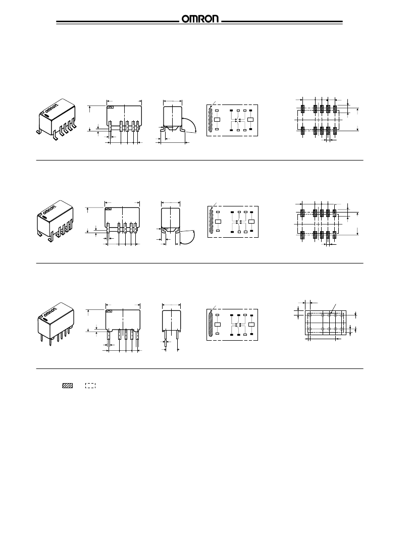
G6S
G6S
Note:
1. Coplanarity is 0.1 mm max.
2. and indicate mounting orientation marks.
G612VDC
II
G612VDC
9
5
°
±
4
°
_
S
+
_
R
+
_
S
+
_
R
+
12VDC
95
°
±
4
°
G6SK-2F,
G6SK-2F-H
Mounting pads
(Top view)
Terminal arrangement/
Internal connections
(Top view)
I
DUAL COIL LATCHING
Orientation mark
1 3 4 5 6
.65
(.026)
2.54
(.10)
5.08
(.20)
1.0
(.039)
8.0
(.315)
2.2
(.087)
14.8
0.2
(.583) max.
7.3
±
0.2
(.287) max.
2.54
(.10)
9.2
0.2
(.362)
max.
.50
(.019)
5.08
(.20)
2.54
(.10)
12 10 9 8 7
0.25
(.01)
2.54
(.10)
2.54
(.10)
Orientation mark
9.2
0.2
(.362)
max.
.65
(.026)
2.54
(.10)
5.08
(.20)
2.2
(.087)
6.1
(.24)
1.0
(.039)
14.8
0.2
(.583) max.
7.3
0.2
(.287) max.
2.54
(.10)
12 10 9 8 7
1 3 4 5 6
0.25
(.01)
2.54
(.10)
2.54
(.10)
2.54
(.10)
.50
(.019)
5.08
(.20)
1.25
±
0.2
(.05)
9.2
+0.5
-0.3
1.25
±
0.2
(.05)
4.9
+0.3
-0.5
G6SK-2G,
G6SK-2G-H
Mounting pads
(Top view)
Terminal arrangement/
Internal connections
(Top view)
Orientation mark
9.2
0.2
(.362)
max.
.65
(.026)
2.54
(.10)
5.08
(.20)
12..7
±
0.1
1.0
(.039)
14.8
0.2
(.583) max.
7.3
0.2
(.287) max.
2.54
(.10)
12 10 9 8 7
1 3 4 5 6
+
S
-
0.25
(.01)
2.54
(.10)
2.54
(.10)
2.54
(.10)
.50
(.019)
5.08
(.20)
G6SK-2,
G6SK-2-H
Mounting holes
(Bottom view)
Terminal arrangement/
Internal connections
(Bottom view)
5.08
(.20)
123456
123456
1.11
(.04)
Unit: mm (inch)
10 - 1 dia.
holes
+
R
-
相關(guān)PDF資料 |
PDF描述 |
|---|---|
| G6SK-22-DC4.5 | |
| G6SK-22-DC5 | |
| G6SK-22-DC6 | |
| G6SK-22-DC9 | |
| G6S-2 | Low Signal Relay |
相關(guān)代理商/技術(shù)參數(shù) |
參數(shù)描述 |
|---|---|
| G6SK-22-DC4.5 | 制造商:未知廠家 制造商全稱:未知廠家 功能描述: |
| G6SK-22-DC5 | 制造商:未知廠家 制造商全稱:未知廠家 功能描述: |
| G6SK-22-DC6 | 制造商:未知廠家 制造商全稱:未知廠家 功能描述: |
| G6SK-22-DC9 | 制造商:未知廠家 制造商全稱:未知廠家 功能描述: |
| G6SK-23DC | 制造商:Omron Electronic Components LLC 功能描述:Relay DPDT DIP dw-latched,2A 3Vdc |
發(fā)布緊急采購,3分鐘左右您將得到回復(fù)。