- 您現(xiàn)在的位置:買賣IC網(wǎng) > PDF目錄370215 > FP80 Filter & Ring Core Chokes PDF資料下載
參數(shù)資料
| 型號(hào): | FP80 |
| 英文描述: | Filter & Ring Core Chokes |
| 中文描述: | 過濾器 |
| 文件頁數(shù): | 3/5頁 |
| 文件大小: | 119K |
| 代理商: | FP80 |
Accessories
Filter & Ring Core Chokes FP L and LP Series
REV. SEP 29, 2003
Page 3 of 5
Typical Application
The example in figure Reduction of voltage interference by
FP filtersshows a switching regulator operating from a bat-
tery (R
i
<
0.5
) with long supply lines (e.g. 2 m). The result-
ing superimposed interference voltage U
SL
may be meas-
ured at the regulators input. The connection of a filter in
front of the power supply will reduce this interference ac-
cordingly:
1. The regulator's source impedance is mainly inductive
because of the low battery impedance and the long sup-
ply lines. It can be calculated as follows:
l Z
Line
l
2
π
f
S
L
Line
2 l
l Z
Line
l
2
π
(150 10
3
) 10
-6
2 2
3.8
f
S
:
Switching frequency (150 kHz)
L
Line
: Supply line inductance (typically 1μH/m)
l:
Length of single supply line (twice for posi-
tive and negative path)
Fig. 3
Reduction of voltage interference by FP filters
Vi+
Gi–
Vo+
Go–
PSR
R
L
U
o
U
Filter
Uio
Uii
Gi
U
s
2 l
Z
Line
12011
2. This example shows, that with an inductive source im-
pedance of 3.8
, the insertion of the filter results in an
interference voltage reduction of approx. 18 dB (see
fig.: Interference voltage reduction with FP filters at f =
150 kHz).
3. The original superimposed interference voltage will be
reduced by a factor of approx. 8:
U
SF
= U
SL
10
–18/20
[V]
Electrical Data Ring Core Chokes
General Condition: T
A
= 25°C unless otherwise specified
Table 3: Ring core chokes
Characteristics
Conditions
L20-7/LP 20-7
min
typ
LP34-3
typ
LP183
typ
max
min
max
min
max
Unit
I
Ln
Rated current
1
L= 0.75 L
o
7
3
8
A DC
R
L
Ohmic resistance
5
5.5
6
18
20
22
2
×
2.9 2
×
4.2 2
×
5.5
2
×
95 2
×
183 2
×
245
my
L
o
D
TI
No load inductance
I
L
= 0, T
C min
...T
C max
18
20
22
30
34
38
μH
Current specific case
temp. increase
1
0.082
0.68
0.19
K/A
2
T
A
Amb. temperature
1
I
L
= I
Ln
–40
106
–40
104
–40
98
°C
T
C
Case temperature
–40
110
–40
110
–40
110
T
S
Storage temperature
–40
110
–40
110
–40
110
1
If the choke is not operating at the rated current I
Ln
, the maximum ambient temperature T
A max
and the maximum direct current I
L max
change according to the following equations:
I
L max
=
D
TI
T
C max
–T
A max
T
A max
= T
C max
– I
L2 max
D
TI
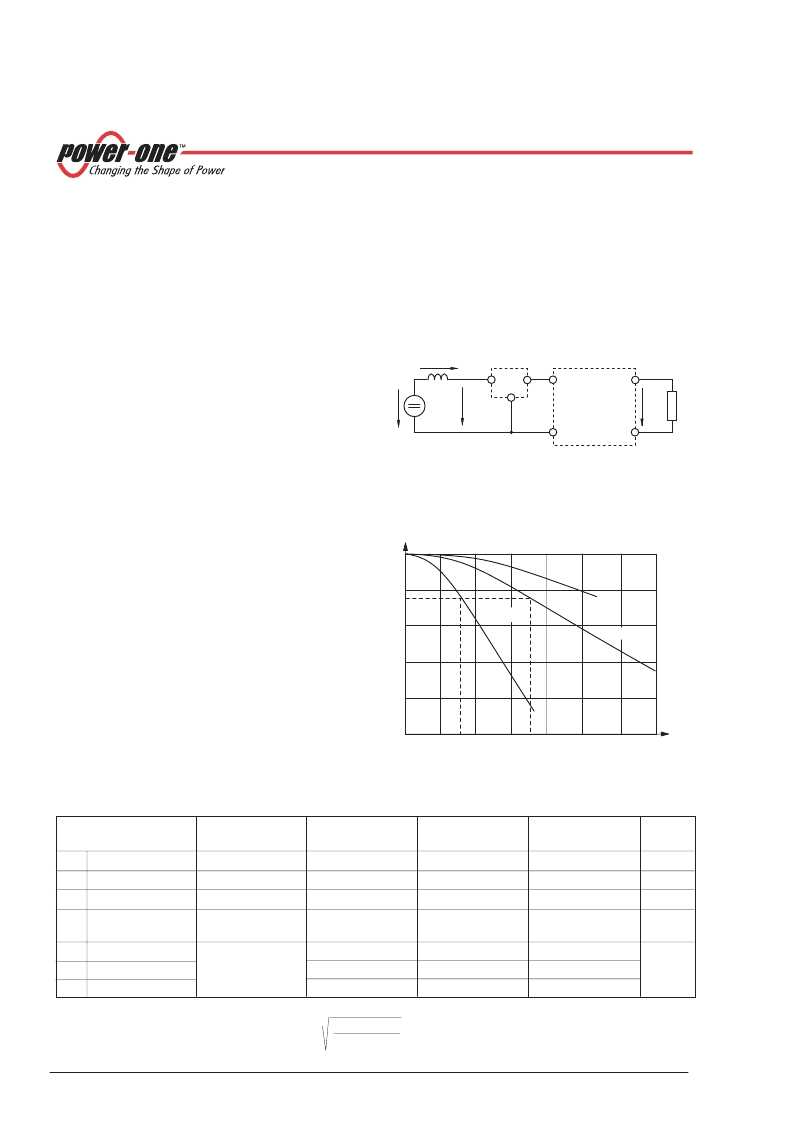
Low-Loss Ring Core Chokes L/LP-Series
The ring core chokes, in combination with a capacitor, may
easily be used for application specific LC filters at the input
or output of switched mode power supplies. All chokes are
suitable for PCB mounting. They are either moulded into
plastic cases or isolated from the PCB by means of an iso-
lation pad.
Series L/LP20-7 and LP34-3 are intended for use as differ-
ential mode filters and the current compensated choke
LP183 enables attenuation of common mode interference.
80
75
60
40
0
20
0
2
6
4
12
8
10
14
100
7
3
LP34-3
LP183
L/LP20-7
12012
L/L
o
[%]
I
L
I
L
I
L
[A]
Fig. 4
Choke inductance versus current
相關(guān)PDF資料 |
PDF描述 |
|---|---|
| FP210-D-250-22 | ?Differential Magnetoresistive Sensor? |
| FP210-L-100-22 | ?Differential Magnetoresistive Sensor? |
| FP210 | NPN Epitaxial Planar Silicon Transistor Driver Applications |
| FP210L100-22 | Differential Magnetoresistive Sensor |
| FP210D250-22 | Differential Magnetoresistive Sensor |
相關(guān)代理商/技術(shù)參數(shù) |
參數(shù)描述 |
|---|---|
| FP80 | 制造商:ebm-papst Inc 功能描述:FILTERS 80MM PK5 |
| FP801 | 制造商:DAESAN 制造商全稱:Daesan Electronics Corp. 功能描述:CURRENT 8.0 Amperes VOLTAGE 50 to 1000 Volts |
| FP8015-V19 | 制造商:HENKEL 功能描述:3549 - REWORKABLE UNDERFILL - 30ML - IDH# 910487 |
| FP802 | 制造商:DAESAN 制造商全稱:Daesan Electronics Corp. 功能描述:CURRENT 8.0 Amperes VOLTAGE 50 to 1000 Volts |
| FP803 | 制造商:DAESAN 制造商全稱:Daesan Electronics Corp. 功能描述:CURRENT 8.0 Amperes VOLTAGE 50 to 1000 Volts |
發(fā)布緊急采購(gòu),3分鐘左右您將得到回復(fù)。