- 您現(xiàn)在的位置:買賣IC網(wǎng) > PDF目錄64890 > FBA1J4BTTE471P (KOA SPEER ELECTRONICS INC) 4 FUNCTIONS, 0.1 A, FERRITE CHIP PDF資料下載
參數(shù)資料
| 型號: | FBA1J4BTTE471P |
| 廠商: | KOA SPEER ELECTRONICS INC |
| 元件分類: | 數(shù)據(jù)傳輸濾波器 |
| 英文描述: | 4 FUNCTIONS, 0.1 A, FERRITE CHIP |
| 封裝: | EIA STD PACKAGE SIZE 0603 |
| 文件頁數(shù): | 3/3頁 |
| 文件大?。?/td> | 61K |
| 代理商: | FBA1J4BTTE471P |
270
KOA Speer Electronics, Inc. Bolivar Drive P.O. Box 547 Bradford, PA 16701 USA 814-362-5536 Fax: 814-362-8883 www.koaspeer.com
Specifications given herein may be changed at any time without prior notice. Please confirm technical specifications before you order and/or use.
11/01/03
FBA
ferrite bead array
environmental applications (continued)
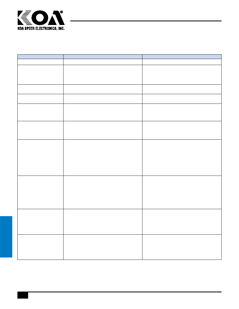
Performance Characteristics
Parameter
Terminal Strength
(hanging test)
Appearance: The terminal electrode shall not break
off, nor shall there be damage to the body.
Type:
W(kgf):
Time:
1206
1.5
30 seconds ± 2 seconds
Terminal Strength
(push test)
Appearance: There shall be no evidence of
mechanical degradations to terminals or body.
Type:
W(kgf):
Time:
1206
2.3
60 seconds
Solvent Resistance
Change in Impedance: Relative to value before
test ±10%
Cleaning by:
Washer: Ultrasonic washer (100W)
Solvent: Isopropyl alcohol
Time: 3 minutes
Insulation Resistance
Insulation Resistance: Min. 1G ohms
Requirement
Test Method
Bending Strength
Appearance: There shall be no physical
or mechanical damage.
Impedance: Relative to initial value
before test ±10%
Board: 90 x 40 x 1.6mm
Bend: 1mm
Time: 5 sec
Mechanical Shock
Appearance: There shall be no physical
or mechanical damage.
Impedance: Relative to initial value
before test ±10%
Force: 50G
Time: 11 msec
There shall be 3 shocks in each of 6 directions
(18 shocks total)
Vibration
Impedance: Relative to initial value ±10%
Only endurance conditioning by sweeping shall
be made. The entire frequency range from
10 - 2,000 Hz, return to 10 Hz in 20 minutes
(this will constitute one cycle).
Amplitude: 15G
The test shall have a 15G peak and shall be
applied for a period of 4 hours (12 cycles) in each
of 3 mutually perpendicular directions (a total of
36 cycles within a total of 12 hours).
Thermal Shock
Appearance: There shall be no physical
or mechanical damage.
Impedance: Relative to initial value ±20%
DCR: The DCR shall not exceed initial specified value.
Testing of the parts will be made at 0 hours, 250
hours and 500 hours. Before testing, the parts shall
be allowed to cool to room temperature for 24 hours.
Step:
Temperature:
Time:
1-start
-40°C ± 2°C
—
2-hold
-40°C ± 2°C
30 minutes ± 5 minutes
3-transfer
—
0.5 minutes maximum
4-hold
±105°C ± 2°C
30 minutes ± 5 minutes
5-transfer
—
0.5 minutes maximum
Steps 1 thru 5 constitute one complete cycle and the
test shall consist of a total of 500 cycles.
Load Humidity
Appearance: There shall be no physical
or mechanical damage.
Impedance: Relative to initial value ±15%
Measurements shall be taken at 0 hours, 250 hours,
500 hours and 1,000 hours and shall meet the
conditions stated above.
Temperature: ±85°C ± 2°C
Relative Humidity: 85%
Time: 1,000 hours total
Apply: 100% rated current
Life Test
Appearance: There shall be no physical
or mechanical damage.
Impedance: Relative to initial value ±15%
Measurements shall be taken at 0 hours, 250 hours,
500 hours and 1,000 hours and shall meet the
conditions stated above.
Temperature: ±85°C ± 2°C
Time: 1,000 hours total
Apply: 100% rated current
EMI/EMC
filtering
相關(guān)PDF資料 |
PDF描述 |
|---|---|
| FBF325 | 1 FUNCTIONS, 114.99 MHz, SAW FILTER |
| FBF331 | 1 FUNCTIONS, 160 MHz, SAW FILTER |
| FBF334 | 1 FUNCTIONS, 70 MHz, SAW FILTER |
| FBF334 | 1 FUNCTIONS, 70 MHz, SAW FILTER |
| FBG403 | 1 FUNCTIONS, 70 MHz, SAW FILTER |
相關(guān)代理商/技術(shù)參數(shù) |
參數(shù)描述 |
|---|---|
| FBA1J4BTTE600P | 制造商:KOA 制造商全稱:KOA Speer Electronics, Inc. 功能描述:ferrite bead array |
| FBA1J4BTTE601P | 制造商:KOA 制造商全稱:KOA Speer Electronics, Inc. 功能描述:ferrite bead array |
| FBA-24-ALE-050 | 制造商:American Technical Ceramics Corp 功能描述: |
| FBA-24-ALE-060 | 制造商:American Technical Ceramics Corp 功能描述: |
| FBA42060 | 功能描述:功率因數(shù)校正 IC PFC SPM 45Series for 1-Phase Boost PFC RoHS:否 制造商:Fairchild Semiconductor 開關(guān)頻率:300 KHz 最大功率耗散: 最大工作溫度:+ 125 C 安裝風(fēng)格:SMD/SMT 封裝 / 箱體:SOIC-8 封裝:Reel |
發(fā)布緊急采購,3分鐘左右您將得到回復(fù)。