- 您現(xiàn)在的位置:買賣IC網(wǎng) > PDF目錄370147 > FAN8001DTF Servo/Spindle Motor Controller/Driver PDF資料下載
參數(shù)資料
| 型號: | FAN8001DTF |
| 英文描述: | Servo/Spindle Motor Controller/Driver |
| 中文描述: | 伺服/主軸電機控制器/驅(qū)動器 |
| 文件頁數(shù): | 66/191頁 |
| 文件大?。?/td> | 2018K |
| 代理商: | FAN8001DTF |
第1頁第2頁第3頁第4頁第5頁第6頁第7頁第8頁第9頁第10頁第11頁第12頁第13頁第14頁第15頁第16頁第17頁第18頁第19頁第20頁第21頁第22頁第23頁第24頁第25頁第26頁第27頁第28頁第29頁第30頁第31頁第32頁第33頁第34頁第35頁第36頁第37頁第38頁第39頁第40頁第41頁第42頁第43頁第44頁第45頁第46頁第47頁第48頁第49頁第50頁第51頁第52頁第53頁第54頁第55頁第56頁第57頁第58頁第59頁第60頁第61頁第62頁第63頁第64頁第65頁當前第66頁第67頁第68頁第69頁第70頁第71頁第72頁第73頁第74頁第75頁第76頁第77頁第78頁第79頁第80頁第81頁第82頁第83頁第84頁第85頁第86頁第87頁第88頁第89頁第90頁第91頁第92頁第93頁第94頁第95頁第96頁第97頁第98頁第99頁第100頁第101頁第102頁第103頁第104頁第105頁第106頁第107頁第108頁第109頁第110頁第111頁第112頁第113頁第114頁第115頁第116頁第117頁第118頁第119頁第120頁第121頁第122頁第123頁第124頁第125頁第126頁第127頁第128頁第129頁第130頁第131頁第132頁第133頁第134頁第135頁第136頁第137頁第138頁第139頁第140頁第141頁第142頁第143頁第144頁第145頁第146頁第147頁第148頁第149頁第150頁第151頁第152頁第153頁第154頁第155頁第156頁第157頁第158頁第159頁第160頁第161頁第162頁第163頁第164頁第165頁第166頁第167頁第168頁第169頁第170頁第171頁第172頁第173頁第174頁第175頁第176頁第177頁第178頁第179頁第180頁第181頁第182頁第183頁第184頁第185頁第186頁第187頁第188頁第189頁第190頁第191頁
FAN5061
14
P
with I
Detect
≈
50μA, I
SC
is the desired current limit, and
R
DS,on
the high-side MOSFET’s on resistance. Remember to
make the R
S
large enough to include the effects of initial tol-
erance and temperature variation on the MOSFET’s R
DS,on
.
Alternately, use of a sense resistor in series with the source
of the MOSFET eliminates this source of inaccuracy in the
current limit.
As an example, Figure 4 shows the typical characteristic of
the DC-DC converter circuit with an FDB6030L high-side
MOSFET (R
DS
= 20m
maximum at 25°C * 1.25 at 75°C =
25m
) and a 8.2K
R
S
.
Figure 4. FAN5061 Short Circuit Characteristic
The converter exhibits a normal load regulation characteristic
until the voltage across the MOSFET exceeds the internal
short circuit threshold of 50μA * 8.2K
= 410mV, which
occurs at 410mV/25m
= 16.4A. (Note that this current limit
level can be as high as 410mV/15m
= 27A, if the MOSFET
has typical R
DS,on
rather than maximum, and is at 25°C).
If the current exceeds this limit for more than 30μsec, the
FAN5061 shuts down all of its outputs, including its linear
regulators. They remain shut down until power is recycled.
Similarly, if any of the linear regulator outputs are loaded
heavily enough that their output voltage drops below 80% of
nominal, all FAN5061 outputs, including the switcher, are
shut off and remain off until power is recycled.
Schottky Diode Selection
The application circuit of Figure 1 shows a Schottky diode,
D1, which is used as a free-wheeling diode to assure that the
body-diode in Q2 does not conduct when the upper MOSFET
is turning off and the lower MOSFET is turning on. It is
undesirable for this diode to conduct because its high forward
voltage drop and long reverse recovery time degrades efficiency,
and so the Schottky provides a shunt path for the current.
Since this time duration is very short, the selection criterion
for the diode is that the forward voltage of the Schottky at
the output current should be less than the forward voltage of
the MOSFET’s body diode.
Output Filter Capacitors
The output bulk capacitors of a converter help determine its
output ripple voltage and its transient response. It has already
been seen in the section on selecting an inductor that the ESR
helps set the minimum inductance, and the capacitance value
helps set the maximum inductance. For most converters,
however, the number of capacitors required is determined by
the transient response and the output ripple voltage, and these
are determined by the ESR and not the capacitance value.
That is, in order to achieve the necessary ESR to meet the
transient and ripple requirements, the capacitance value
required is already very large.
The most commonly used choice for output bulk capacitors is
aluminum electrolytics, because of their low cost and low ESR.
The only type of aluminum capacitor used should be those that
have an ESR rated at 100kHz. Consult Application Bulletin
AB-14 for detailed information on output capacitor selection.
The output capacitance should also include a number of
small value ceramic capacitors placed as close as possible to
the processor; 0.1μF and 0.01μF are recommended values.
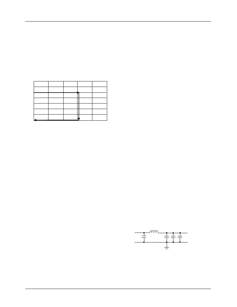
Input Filter
The DC-DC converter design may include an input inductor
between the system +5V supply and the converter input as
shown in Figure 5. This inductor serves to isolate the +5V
supply from the noise in the switching portion of the DC-DC
converter, and to limit the inrush current into the input capac-
itors during power up. A value of 2.5μH is recommended.
It is necessary to have some low ESR aluminum electrolytic
capacitors at the input to the converter. These capacitors
deliver current when the high side MOSFET switches on.
Figure 5 shows 3 x 1000μF, but the exact number required
will vary with the speed and type of the processor. For the
top speed Katmai and Coppermine, the capacitors should be
rated to take 9A and 6A of ripple current respectively.
Capacitor ripple current rating is a function of temperature,
and so the manufacturer should be contacted to find out the
ripple current rating at the expected operational temperature.
For details on the design of an input filter, refer to Applica-
tions Bulletin AB-15.
Figure 8. Input Filter
V
O
Output Current (A)
0 5 10 15 20 25
2.5
μ
H
5V
0.1
μ
F
1000
μ
F, 10V
Electrolytic
Vin
相關(guān)PDF資料 |
PDF描述 |
|---|---|
| FAN8002D2 | Servo Motor Controller/Driver |
| FAN8005D2 | Servo Motor Controller/Driver |
| FAN8035L | MOTOR CONTROLLER |
| FAN8039D3 | Servo/Spindle Motor Controller/Driver |
| FAN8800 | |
相關(guān)代理商/技術(shù)參數(shù) |
參數(shù)描述 |
|---|---|
| FAN8002D2 | 制造商:未知廠家 制造商全稱:未知廠家 功能描述:Servo Motor Controller/Driver |
| FAN8004 | 功能描述:馬達/運動/點火控制器和驅(qū)動器 Motor Driver 4Ch BTL+1Ch DC RoHS:否 制造商:STMicroelectronics 產(chǎn)品:Stepper Motor Controllers / Drivers 類型:2 Phase Stepper Motor Driver 工作電源電壓:8 V to 45 V 電源電流:0.5 mA 工作溫度:- 25 C to + 125 C 安裝風格:SMD/SMT 封裝 / 箱體:HTSSOP-28 封裝:Tube |
| FAN8005D2 | 制造商:FAIRCHILD 制造商全稱:Fairchild Semiconductor 功能描述:3-CH Motor Driver |
| FAN8005D2TF | 制造商:未知廠家 制造商全稱:未知廠家 功能描述:Servo Motor Controller/Driver |
| FAN8006D3 | 功能描述:馬達/運動/點火控制器和驅(qū)動器 RoHS:否 制造商:STMicroelectronics 產(chǎn)品:Stepper Motor Controllers / Drivers 類型:2 Phase Stepper Motor Driver 工作電源電壓:8 V to 45 V 電源電流:0.5 mA 工作溫度:- 25 C to + 125 C 安裝風格:SMD/SMT 封裝 / 箱體:HTSSOP-28 封裝:Tube |
發(fā)布緊急采購,3分鐘左右您將得到回復。