- 鎮ㄧ従(xi脿n)鍦ㄧ殑浣嶇疆锛�璨疯常IC缍�(w菐ng) > PDF鐩寗19582 > EPM7032LC44-15T (Altera)IC MAX 7000 CPLD 32 44-PLCC PDF璩囨枡涓嬭級
鍙冩暩(sh霉)璩囨枡
| 鍨嬭櫉锛� | EPM7032LC44-15T |
| 寤犲晢锛� | Altera |
| 鏂囦欢闋佹暩(sh霉)锛� | 21/66闋� |
| 鏂囦欢澶�?銆�?/td> | 0K |
| 鎻忚堪锛� | IC MAX 7000 CPLD 32 44-PLCC |
| 鐢�(ch菐n)鍝佽畩鍖栭€氬憡锛� | MAX 7000 Series Obsolescence 08/Jun/2009 |
| 妯欐簴鍖呰锛� | 390 |
| 绯诲垪锛� | MAX® 7000 |
| 鍙法绋嬮鍨嬶細 | 绯荤当(t菕ng)鍏�(n猫i)鍙法绋� |
| 鏈€澶у欢閬叉檪闁� tpd(1)锛� | 15.0ns |
| 闆诲闆绘簮 - 鍏�(n猫i)閮細 | 4.75 V ~ 5.25 V |
| 閭忚集鍏冧欢/閭忚集濉婃暩(sh霉)鐩細 | 2 |
| 瀹忓柈鍏冩暩(sh霉)锛� | 32 |
| 闁€鏁�(sh霉)锛� | 600 |
| 杓稿叆/杓稿嚭鏁�(sh霉)锛� | 36 |
| 宸ヤ綔婧害锛� | 0°C ~ 70°C |
| 瀹夎椤炲瀷锛� | 琛ㄩ潰璨艰 |
| 灏佽/澶栨锛� | 44-LCC锛圝 褰㈠紩绶氾級 |
| 渚涙噳(y墨ng)鍟嗚ō(sh猫)鍌欏皝瑁濓細 | 44-PLCC锛�16.58x16.58锛� |
| 鍖呰锛� | 绠′欢 |
| 鍏跺畠鍚嶇ū锛� | 544-2287-5 |
绗�1闋�绗�2闋�绗�3闋�绗�4闋�绗�5闋�绗�6闋�绗�7闋�绗�8闋�绗�9闋�绗�10闋�绗�11闋�绗�12闋�绗�13闋�绗�14闋�绗�15闋�绗�16闋�绗�17闋�绗�18闋�绗�19闋�绗�20闋�鐣�(d膩ng)鍓嶇21闋�绗�22闋�绗�23闋�绗�24闋�绗�25闋�绗�26闋�绗�27闋�绗�28闋�绗�29闋�绗�30闋�绗�31闋�绗�32闋�绗�33闋�绗�34闋�绗�35闋�绗�36闋�绗�37闋�绗�38闋�绗�39闋�绗�40闋�绗�41闋�绗�42闋�绗�43闋�绗�44闋�绗�45闋�绗�46闋�绗�47闋�绗�48闋�绗�49闋�绗�50闋�绗�51闋�绗�52闋�绗�53闋�绗�54闋�绗�55闋�绗�56闋�绗�57闋�绗�58闋�绗�59闋�绗�60闋�绗�61闋�绗�62闋�绗�63闋�绗�64闋�绗�65闋�绗�66闋�
28
Altera Corporation
MAX 7000 Programmable Logic Device Family Data Sheet
Notes to tables:
(1)
(2)
Minimum DC input voltage on I/O pins is 鈥�0.5 V and on 4 dedicated input pins is 鈥�0.3 V. During transitions, the
inputs may undershoot to 鈥�2.0 V or overshoot to 7.0 V for input currents less than 100 mA and periods shorter than
20 ns.
(3)
Numbers in parentheses are for industrial-temperature-range devices.
(4)
VCC must rise monotonically.
(5)
The POR time for all 7000S devices does not exceed 300 渭s. The sufficient VCCINT voltage level for POR is 4.5 V. The
device is fully initialized within the POR time after VCCINT reaches the sufficient POR voltage level.
(6)
3.3-V I/O operation is not available for 44-pin packages.
(7)
The VCCISP parameter applies only to MAX 7000S devices.
(8)
During in-system programming, the minimum DC input voltage is 鈥�0.3 V.
(9)
These values are specified under the MAX 7000 recommended operating conditions in Table 14 on page 26.
(10) The parameter is measured with 50% of the outputs each sourcing the specified current. The IOH parameter refers
to high-level TTL or CMOS output current.
(11) The parameter is measured with 50% of the outputs each sinking the specified current. The IOL parameter refers to
low-level TTL, PCI, or CMOS output current.
(12) When the JTAG interface is enabled in MAX 7000S devices, the input leakage current on the JTAG pins is typically
鈥�60 渭A.
(13) Capacitance is measured at 25掳 C and is sample-tested only. The OE1 pin has a maximum capacitance of 20 pF.
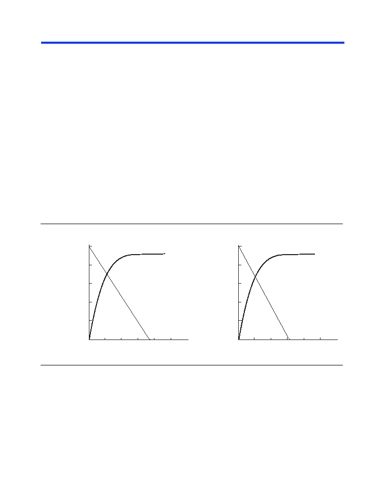
Figure 11 shows the typical output drive characteristics of MAX 7000
devices.
Figure 11. Output Drive Characteristics of 5.0-V MAX 7000 Devices
Timing Model
MAX 7000 device timing can be analyzed with the Altera software, with a
variety of popular industry-standard EDA simulators and timing
analyzers, or with the timing model shown in Figure 12. MAX 7000
devices have fixed internal delays that enable the designer to determine
the worst-case timing of any design. The Altera software provides timing
simulation, point-to-point delay prediction, and detailed timing analysis
for a device-wide performance evaluation.
VO Output Voltage (V)
12345
30
60
90
150
120
VCCIO = 3.3 V
IOL
IOH
Room Temperature
3.3
VO Output Voltage (V)
12345
30
60
90
150
120
VCCIO = 5.0 V
IOL
IOH
Room Temperature
I O
Typical
Output
Current (mA)
I O
Typical
Output
Current (mA)
鐩搁棞(gu膩n)PDF璩囨枡 |
PDF鎻忚堪 |
|---|---|
| TPSB156M020R0500 | CAP TANT 15UF 20V 20% 1210 |
| M5-512/256-10SAC | IC CPLD ISP 512MC 256IO 352SBGA |
| MIC5258-1.2BM5 TR | IC REG LDO 1.2V .15A SOT23-5 |
| ISPLSI 5512VA-110LQ208 | IC PLD ISP 288I/O 8.5NS 208PQFP |
| EPM7032LC44-15 | IC MAX 7000 CPLD 32 44-PLCC |
鐩搁棞(gu膩n)浠g悊鍟�/鎶€琛�(sh霉)鍙冩暩(sh霉) |
鍙冩暩(sh霉)鎻忚堪 |
|---|---|
| EPM7032LC44-2 | 鍒堕€犲晢:Altera Corporation 鍔熻兘鎻忚堪: |
| EPM7032LC44-3 | 鍒堕€犲晢:Altera Corporation 鍔熻兘鎻忚堪: |
| EPM7032LC446 | 鍒堕€犲晢:ALTERA 鍔熻兘鎻忚堪:* |
| EPM7032LC44-6 | 鍔熻兘鎻忚堪:IC MAX 7000 CPLD 32 44-PLCC RoHS:鍚� 椤炲垾:闆嗘垚闆昏矾 (IC) >> 宓屽叆寮� - CPLD锛堝京(f霉)闆滃彲绶ㄧ▼閭忚集鍣ㄤ欢锛� 绯诲垪:MAX® 7000 妯欐簴鍖呰:24 绯诲垪:CoolRunner II 鍙法绋嬮鍨�:绯荤当(t菕ng)鍏�(n猫i)鍙法绋� 鏈€澶у欢閬叉檪闁� tpd(1):7.1ns 闆诲闆绘簮 - 鍏�(n猫i)閮�:1.7 V ~ 1.9 V 閭忚集鍏冧欢/閭忚集濉婃暩(sh霉)鐩�:24 瀹忓柈鍏冩暩(sh霉):384 闁€鏁�(sh霉):9000 杓稿叆/杓稿嚭鏁�(sh霉):173 宸ヤ綔婧害:0°C ~ 70°C 瀹夎椤炲瀷:琛ㄩ潰璨艰 灏佽/澶栨:208-BFQFP 渚涙噳(y墨ng)鍟嗚ō(sh猫)鍌欏皝瑁�:208-PQFP锛�28x28锛� 鍖呰:鎵樼洡 |
| EPM7032LC447 | 鍒堕€犲晢:ALTERA 鍔熻兘鎻忚堪:* |
鐧�(f膩)甯冪穵鎬ラ噰璩�锛�3鍒嗛悩宸﹀彸鎮ㄥ皣寰楀埌鍥炲京(f霉)銆�
