- 您現(xiàn)在的位置:買賣IC網(wǎng) > PDF目錄97902 > EL4095C Video Gain Control/Fader(視頻增益控制器/信號漸弱器) PDF資料下載
參數(shù)資料
| 型號: | EL4095C |
| 英文描述: | Video Gain Control/Fader(視頻增益控制器/信號漸弱器) |
| 中文描述: | 視頻增益控制/前后(視頻增益控制器/信號漸弱器) |
| 文件頁數(shù): | 4/24頁 |
| 文件大?。?/td> | 457K |
| 代理商: | EL4095C |

EL4095C
Video Gain ControlFaderMultiplexer
Applications Information
Contd
Stray capacitance at each bVIN terminal should
absolutely be minimized especially in a positive-
gain mode or peaking will occur Similarly the
load capacitance should be minimized If more
than 25 pF of load capacitance must be driven a
load resistor from 100
X to 400X can be added in
parallel with the output to reduce peaking but
some bandwidth degradation may occur
A
‘‘snubber’’ load can alternatively be used This is
a resistor in series with a capacitor to ground
150
X and 100 pF being typical values The ad-
vantage of a snubber is that it does not draw DC
load current A small series resistor low tens of
ohms can also be used to isolate reactive loads
Distortion
The signal voltage range of the aVIN terminals
is within 35V of either supply rail
One must also consider the range of error cur-
rents that will be handled by the bVIN termi-
nals Since the bVIN of a CFA is the output of a
buffer which replicates the voltage at aVIN er-
ror currents will flow into the bVIN terminal
When an input channel has 100% gain assigned
to it only a small error current flows into its neg-
ative input when low gain is assigned to the
channel the output does not respond to the chan-
nel’s signal and large error currents flow
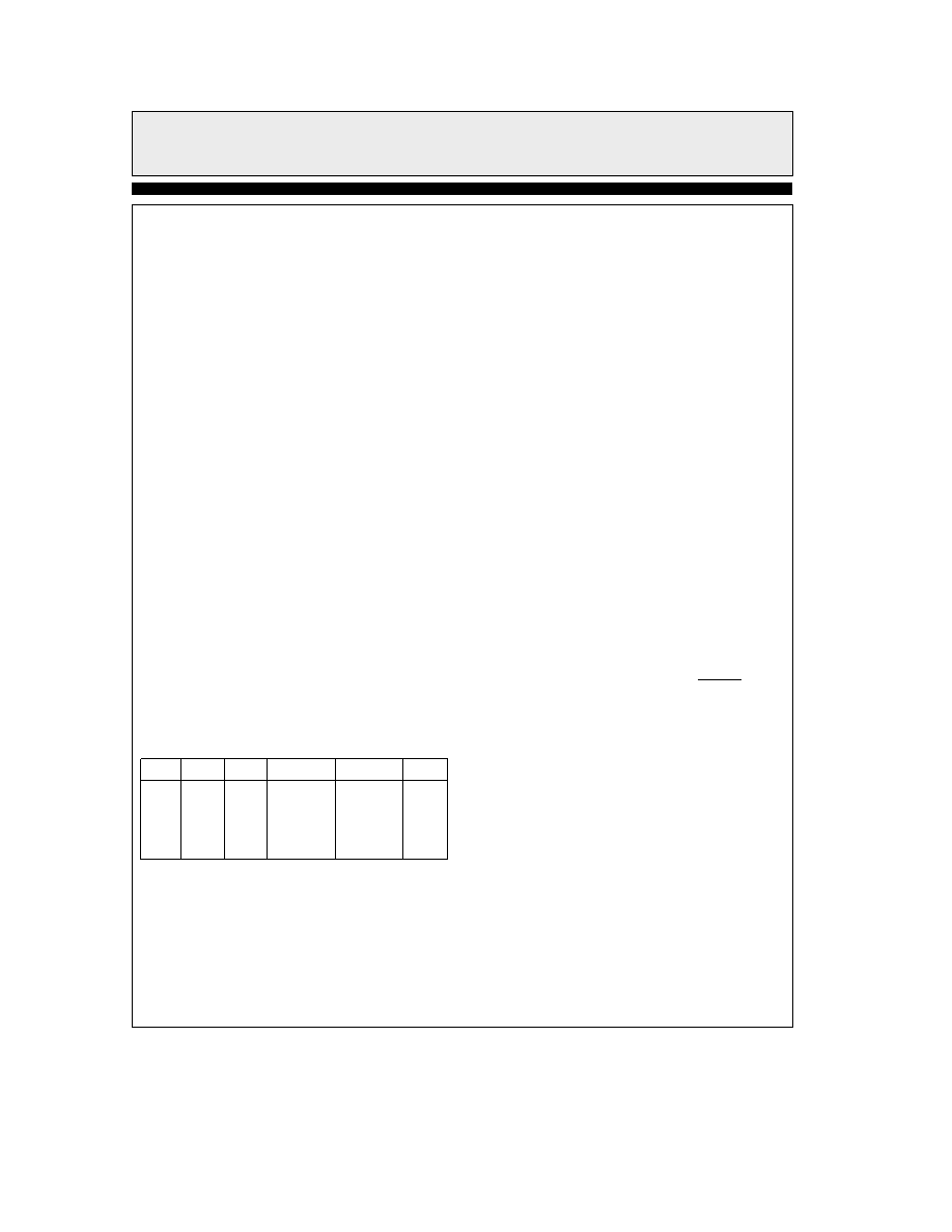
Here are a few idealized examples based on a
gain of a1 for channels A and B and RF e 1kX
for different gain settings
Gain
VINA
VINB
I(bVINA)I (bVINB)VOUT
100%
1V
0
1 mA
1V
75%
1V
0
b
250
mA
750
mA
075V
50%
1V
0
b
500
mA
500
mA
05V
25%
1V
0
b
750
mA
250
mA
025V
0%
1V
0
b
1mA
0
0V
Thus either bVIN can receive up to 1 mA error
current for 1V of input signal and 1 k
X feedback
resistors The maximum error current is 3 mA for
the EL4095 but 2 mA is more realistic The ma-
jor contributor of distortion is the magnitude of
error currents even more important than loading
effects The performance curves show distortion
versus input amplitude for different gains
If maximum bandwidth is not required distor-
tion can be reduced greatly (and signal voltage
range enlarged) by increasing the value of RF
and any associated gain-setting resistor
100% Accuracies
When a channel gain is set to 100% static and
gain errors are similar to those of a simple CFA
The DC output error is expressed by
VOUT Offset e VOS AV a (IBb) RF
The input offset voltage scales with fed-back
gain but the bias current into the negative input
IB
b
adds an error not dependent on gain Gener-
ally IB
b dominates up to gains of about seven
The fractional gain error is given by
EGAIN e (RF a AV RIN b)RF
a
AV RIN)ROL
The gain error is about 03% for a gain of one
and increases only slowly for increasing gain
RINb is the input impedance of the input stage
buffer and ROL is the transimpedance of the am-
plifier 80 k
X and 350 kX respectively
Gain Control Inputs
The gain control inputs are differential and may
be biased at any voltage as long as VGAIN is less
than 25V below Va and 3V above Vb The dif-
ferential input impedance is 55 k
X and a com-
mon-mode impedance is more than 500 k
X With
zero differential voltage on the gain inputs both
signal inputs have a 50% gain factor Nominal
calibration sets the 100% gain of VINA input at
a
05V of gain control voltage and 0% at b05V
of gain control VINB’s gain is complementary to
that of VINA a05V of gain control sets 0% gain
at VINB and b05V gain control sets 100% VINB
gain The gain control does not have a complete-
ly abrupt transition at the 0% and 100% points
There is about 10 mV of ‘‘soft’’ transfer at the
gain endpoints
To obtain the most accurate
100% gain factor or best attenuation of 0% gain
it is necessary to overdrive the gain control input
by about 30 mV This would set the gain control
voltage range as b0565 mV to a0565V
or
30 mV beyond the maximum guaranteed 0% to
100% range
12
相關(guān)PDF資料 |
PDF描述 |
|---|---|
| EL4095 | Video Gain Control/Fader/Multiplexer |
| EL4095CN | FOIL RESISTOR, 500, .1% |
| EL4095CS | Video Gain Control/Fader/Multiplexer |
| EL41 | EL41 |
| EL4331C | Triple 2:1 Mux-Amp AV = 1 |
相關(guān)代理商/技術(shù)參數(shù) |
參數(shù)描述 |
|---|---|
| EL4095CN | 制造商:INTERSIL 制造商全稱:Intersil Corporation 功能描述:Video Gain Control/Fader/Multiplexer |
| EL4095CS | 制造商:INTERSIL 制造商全稱:Intersil Corporation 功能描述:Video Gain Control/Fader/Multiplexer |
| EL40A128S5L6X3PR | 制造商:Avago Technologies 功能描述:INCREMENTAL ENCODER - Bulk |
| EL40PO-30MA-AD24-00415UL | 制造商:Fuji Electric 功能描述: |
| EL41 | 制造商:PHILIPS 制造商全稱:NXP Semiconductors 功能描述:EL41 |
發(fā)布緊急采購,3分鐘左右您將得到回復(fù)。