- 您現(xiàn)在的位置:買賣IC網(wǎng) > PDF目錄11748 > DS30EA101SQX/NOPB (National Semiconductor)IC CABLE EQUALIZER 16LLP PDF資料下載
參數(shù)資料
| 型號: | DS30EA101SQX/NOPB |
| 廠商: | National Semiconductor |
| 文件頁數(shù): | 8/12頁 |
| 文件大?。?/td> | 0K |
| 描述: | IC CABLE EQUALIZER 16LLP |
| 標(biāo)準(zhǔn)包裝: | 4,500 |
| 系列: | * |
DS30BA101
OUT-
IN+
IN-
OUT+
0.1 PF
50:
953:
100:
1 PF
DS30EA101
IN+
IN-
100:
OUT+
OUT-
VCC
100: Differential TP Cable
RVO
SNLS404A – FEBRUARY 2012 – REVISED APRIL 2013
DEVICE OPERATION
The DS30EA101 equalizes data transmitted over copper cables. It automatically adjusts its gain to reverse the
effects of the cable loss and restore the original signal. For proper operation, the launch amplitude of the signal
going into the cable (the signal amplitude prior to the cable attenuation) must be set appropriately. If the signal is
single-ended, its single-ended amplitude must be 800 mVP-P ±10%. If the signal is differential, its differential
amplitude must be 800 mVP-P ±10% (400 mVP-P single-ended).
INPUT INTERFACING
The DS30EA101 accepts either differential or single-ended input. The input must be AC coupled. Figure 3 and
Figure 4 show the typical configurations for differential input and single-ended input, respectively. For single-
ended input, the unused input must be properly terminated as shown.
OUTPUT INTERFACING
The DS30EA101 output signals (OUT+ and OUT- ) are internally terminated 100
LVDS outputs. These outputs
can be DC coupled to most common differential receivers.
LOS AND EN
LOS indicates the loss of signal at the DS30EA101 input. LOS is high when no input signal is present and low
when a valid input signal is detected.
EN can be used to manually disable or enable the OUT+ and OUT- output signals. Applying a high input to EN
will disable the DS30EA101 outputs by forcing the output to a logic 1, and applying a low input to EN will force
the outputs to be active. EN has an internal pulldown to enable the outputs by default.
LOS and EN may be tied together to automatically disable the DS30EA101 outputs when no input signal is
present.
APPLICATION INFORMATION
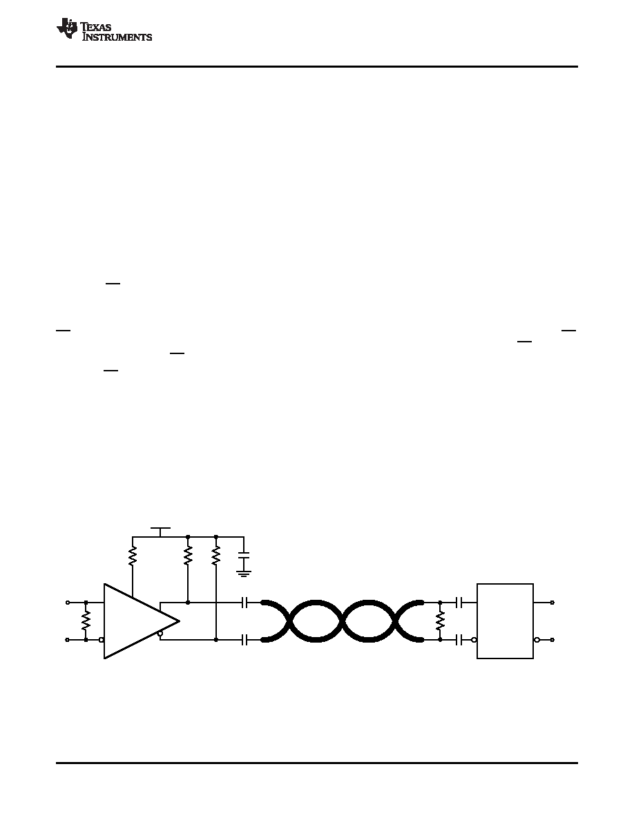
CABLE EXTENDER APPLICATION
The DS30EA101 together with the DS30BA101 form a cable extender chipset optimized for extending serial data
streams from serializer/deseralizer (SerDes) pairs and FPGAs over 100
differential cables and 75 coaxial
cables. Setting the correct DS30BA101 output amplitude and proper cable termination are essential for optimal
operation. Figure 3 shows the recommended chipset configuration for 100
differential cable and Figure 4 shows
the recommended chipset configuration for 75
coaxial cable.
Figure 3. Cable Extender Chipset Application Circuit for 100
Differential Cable
Copyright 2012–2013, Texas Instruments Incorporated
5
Product Folder Links: DS30EA101
相關(guān)PDF資料 |
PDF描述 |
|---|---|
| DS30EA101SQ/NOPB | IC CABLE EQUALIZER 16LLP |
| GRM216R71H472KA01D | CAP CER 4700PF 50V 10% X7R 0805 |
| PIC18F65K80-I/MR | MCU PIC 32KB FLASH 64QFN |
| GRM216R71H222KA01J | CAP CER 2200PF 50V 10% X7R 0805 |
| PIC18F66K22-I/MR | IC MCU 8BIT 64KB FLASH 64QFN |
相關(guān)代理商/技術(shù)參數(shù) |
參數(shù)描述 |
|---|---|
| DS30-FAX | 制造商:Leviton Manufacturing Co 功能描述: |
| DS30FP | 制造商:Eaton Corporation 功能描述:Safety Switch Access/Fuse Puller Kit 30-60A DH 3 Pole |
| DS30-GN | 制造商:Cooper Bussmann 功能描述:DS SERIES TERMINAL BLOCK, 30A, GREEN - Bulk 制造商:COOPER BUSSMANN 功能描述:DS SERIES TERMINAL BLOCK, 30A, GREEN |
| DS30-GY | 制造商:Cooper Bussmann 功能描述:GREY, 600V/30A UL 1000V/32A IEC, #22 - # - Bulk 制造商:COOPER BUSSMANN 功能描述:GREY, 600V/30A UL 1000V/32A IEC, #22 - # |
| DS30-LK | 制造商:Cooper Bussmann 功能描述:BLACK, 600V/30A UL 1000V/32A IEC, #22 - - Bulk 制造商:COOPER INDUSTRIES 功能描述:black, 600V/30A UL 1000V/32A IEC, #22 - 制造商:COOPER BUSSMANN 功能描述:BLACK, 600V/30A UL 1000V/32A IEC, #22 - |
發(fā)布緊急采購,3分鐘左右您將得到回復(fù)。