- 您現(xiàn)在的位置:買賣IC網(wǎng) > PDF目錄374178 > CSR09B565MD (KEMET Corporation) TANTALUM HERMETICALLY SEALED / AXIAL PDF資料下載
參數(shù)資料
| 型號: | CSR09B565MD |
| 廠商: | KEMET Corporation |
| 英文描述: | TANTALUM HERMETICALLY SEALED / AXIAL |
| 中文描述: | 鉭密封/軸流 |
| 文件頁數(shù): | 72/84頁 |
| 文件大小: | 590K |
| 代理商: | CSR09B565MD |
第1頁第2頁第3頁第4頁第5頁第6頁第7頁第8頁第9頁第10頁第11頁第12頁第13頁第14頁第15頁第16頁第17頁第18頁第19頁第20頁第21頁第22頁第23頁第24頁第25頁第26頁第27頁第28頁第29頁第30頁第31頁第32頁第33頁第34頁第35頁第36頁第37頁第38頁第39頁第40頁第41頁第42頁第43頁第44頁第45頁第46頁第47頁第48頁第49頁第50頁第51頁第52頁第53頁第54頁第55頁第56頁第57頁第58頁第59頁第60頁第61頁第62頁第63頁第64頁第65頁第66頁第67頁第68頁第69頁第70頁第71頁當前第72頁第73頁第74頁第75頁第76頁第77頁第78頁第79頁第80頁第81頁第82頁第83頁第84頁
KEMET
PACKAGING INFORMATION
72
KEMET Electronics Corporation, P.O. Box 5928, Greenville, S.C. 29606 (864) 963-6300
KEMET offers Solid Tantalum Capacitors fully compatible for use with automatic insertion machines for radial-lead components. Aris Reeling meets
all requirements of EIA Standard RS-468. KEMET capacitors are wound on a precision made ARIS Reel Package. ARIS Ammo Package is also available.
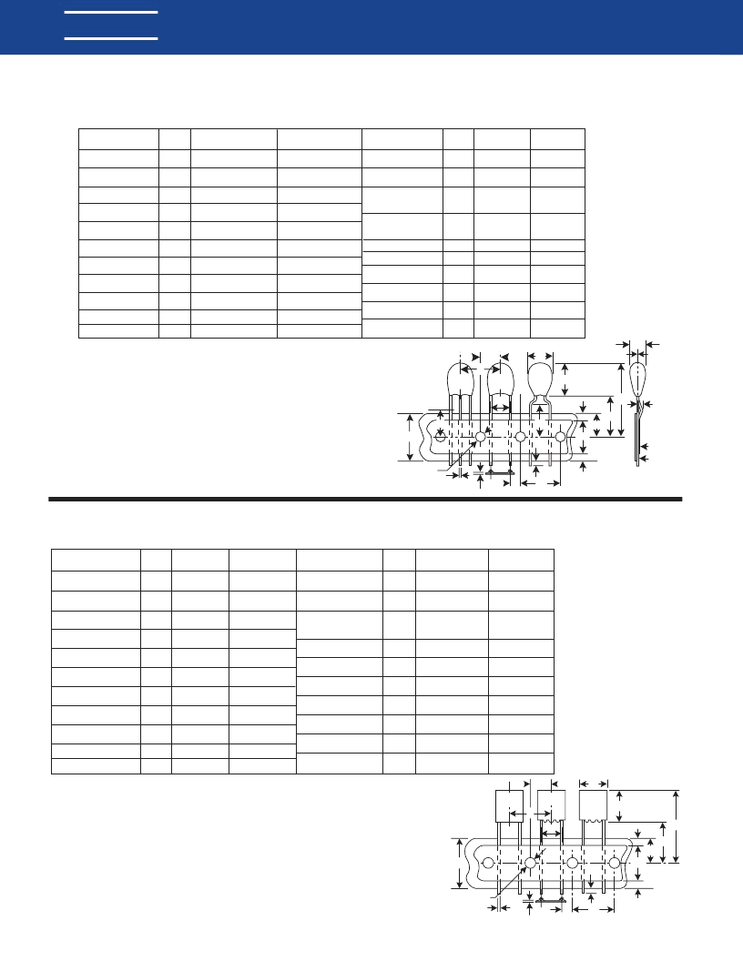
Tantalum Dipped Radial – ARIS Specification (Automatic Radial Insertion System)
Tantalum Dipped Tape and Reel Dimensions in Millimeters & (Inches)
Tantalum Molded Radial – ARIS Specification (Automatic Radial Insertion System)
Tantalum Molded Tape and Reel Dimensions in Millimeters & (Inches)
On polar devices, the positive (+) lead exits from container first.
** Lead spacings are 5.0mm (.197") center-to-center.
On polar devices, the positive (+) lead exits from container first.
* Lead spacings are 2.5mm (.098") center-to-center (T350 A-H)
** Lead spacings are 5.0mm (.197") center-to-center
F Dimensions:
0.100"
±
.015
0.125"
±
.015
0.200"
±
.015
0.250"
±
.015"
0.100 "
±
.015 (3 leaded)
P1 Dimensions:
Lead
Spacing
0.100" – 0.200
±
.028"
0.125" – 0.187
±
.028"
0.200" – 0.150
±
.028"
0.250" – 0.125
±
.028"
0.100" – 0.100
±
.028" ( 3 leaded)
T330**
T340**
T370
P
2
H
A
W
1
W
0
W
2
W
2
P
0
T
d
L
1
A
1
P
H
1
W
D
0
P
1
F
T350/1*
T352/3/4/5/6**
T396/8*
1MM Max.
Tape
Carrier
T
0
H
P
2
H
A
W
0
W
2
W
2
P
0
T
d
L
1
A
1
P
H
1
W
1
P
1
F
W
D
0
L
H
0
Body Height (1)
Body Width (1)
Sprocket Hole
Diameter
Lead Diameter
Lead Center (5)
Component Base
to Tape Center (2)(4)(6)
Lead Standoff
Height
Component Height
Above Tape Center
Component Alignment
Front to Rear
Cut Out Length
Lead Protrustion
Dimension
Symbol
A
Nominal
mm (inch)
10.50 (.413)
Tolerance
mm (inch)
±
.38 (
±
.015)
Maximum
Maximum
±
.38
±
(.015)
±
0.3 (
±
.012)
Dimension
Component Pitch (5)
Symbol
P
Nominal
mm (inch)
12.7 (.500)
Tolerance
mm (inch)
±
1.0 (
±
.039)
Sprocket Hole
Pitch (3)
Sprocket Hole
Center to Lead
Center (4) (5)
Sprocket Hole Center
to Component Center
Body Thickness
Total Tape Thickness
Carrier Tape Width
Hold-Down Tape
Width
Sprocket Hole
Location
Hold-Down Tape
Location
A1
D0
d
F
H
H0
H1
H
L
L1
15.24 (.600)
4.0 (.157)
0.51 or 0.64
(.020) (.025)
5.0 2.5
(.197) (.098)
18.0 (.709)
N/A
32.25 (1.270)
0
11.0 (.433)
2.0 (.079)
±
0.05 or
±
.03
(
±
.001)
+ 0.8/ - 0.2
(+ .032/ -.008)
Reference Only
Maximum
±
2.0
(
±
.079)
Maximum
Maximum
12.7 (.500)
3.85 4.76 5.1
(.152) (.188) (.201)
6.35 (.250)
6.35 (.250)
0.7 (0.28)
18.0 (.709)
15 or 6
(.561) (.236)
9.0 (.354)
3.0 or 12.0
(.118) (.472)
P0
P1
P2
T0
T
W
W0
W1
W2
±
0.3 (
±
.012)
±
0.7 (
±
.028)
±
1.3 (
±
.051)
±
1.3 Maximum
±
.02 (
±
.008)
+ 1.0/-0.5
(+.039/-.020)
+ 1.0/-0.8
(+.039/.031)
+.075/-0.5
(+.030/-.020)
Maximum
Notes: (1) See page 50 for T330, page 53 for T340 and page 59 for T35X specific dimensions.
(2) Reference Only
(3) Cumulative pitch error
±
1.0mm (.039") maximum in 20 consecutive sprocket hole locations.
(4) Measured at bottom of standoff.
(5) P, P1 and F measured at egress from carrier tape.
(6) H dimensions for T370 D and E 16.5mm
±
0.5mm (0.650"
±
0.020")
Body Height (1)
Body Width (1)
Sprocket Hole
Diameter
Lead Diameter
Lead Center (4)
Component Base
to Tape Center (4)
Lead Standoff
Height
Component Height
Above Tape Center
Component Alignment
Front to Rear
Cut Out Length
Lead Protrustion
Notes: (1) See page 62 for T35X and page 69 for T39X specific dimensions.
(2) Cumulative pitch error
±
1.0mm (.039) maximum in 20 consecutive sprocket hole locations.
(3) Measured at bottom of standoff.
(4) P1 and F measured at egress from carrier tape.
(5) P and P2 measured at egress from carrier tape.
Dimension
Symbol
A
Nominal
mm (inch)
Tolerance
mm (inch)
Dimension
Component Pitch (5)
Symbol
P
Nominal
mm (inch)
12.7 (.500)
Tolerance
mm (inch)
±
1.0 (
±
.039)
Sprocket Hole
Pitch (2)
Sprocket Hole
Center to Lead
Center (3) (4)
Sprocket Hole Center
to Component (5)
Center
Body Thickness
Total Tape Thickness
Carrier Tape Width
Hold-Down Tape
Width
Sprocket Hole
Location
Hold-Down Tape
Location
A1
D0
d
F
H
H0
H1
H
L
L1
17.0 (0.67)
10.2 (0.40)
4.0 (.157)
0.51 or 0.64
(.020) (.025)
See Note Below
C-7301 C-7303
16.0 (.630) 18.0 (.709)
C-7301 C-7303
16.0 (.630) 18.0 (.709)
32.25 (1.270)
0
11.0 (.433)
1.0 (.039)
Maximum
Maximum
±
0.3 (
±
.012)
±
0.05 (.002)
C-7301 C-7303
±
0.5 (
±
.020) Minimum
C-7301 C-7303
±
0.5 (
±
.020) Minimum
Maximum
1.0 (.039)
Maximum
Maximum
12.7 (.500)
See Note
Below
See Note
Below
10.2 (.400)
0.7 (0.28)
18.0 (.709)
15mm or 6mm
(.561) (.236)
9.0 (.354)
12mm (.472)
P0
P1
P2
T0
T
W
W0
W1
W2
±
0.3 (
±
.012)
±
0.7 (
±
.028)
Maximum
±
.02 (.008)
+ 1.0/-0.5
(+.039/-.020)
+ 1.0/-0.8
(+.039/-.031)
+.075/-0.5
(+.030/-.020)
Maximum
相關(guān)PDF資料 |
PDF描述 |
|---|---|
| CSR09B565MM | TANTALUM HERMETICALLY SEALED / AXIAL |
| CSR09B565MP | TANTALUM HERMETICALLY SEALED / AXIAL |
| CSR13B565JR | TANTALUM HERMETICALLY SEALED / AXIAL |
| CSR13B565JS | TANTALUM HERMETICALLY SEALED / AXIAL |
| CSR13B565KM | TANTALUM HERMETICALLY SEALED / AXIAL |
相關(guān)代理商/技術(shù)參數(shù) |
參數(shù)描述 |
|---|---|
| CSR09B565MM | 制造商:KEMET 制造商全稱:Kemet Corporation 功能描述:TANTALUM HERMETICALLY SEALED |
| CSR09B565MP | 制造商:KEMET 制造商全稱:Kemet Corporation 功能描述:TANTALUM HERMETICALLY SEALED |
| CSR09B565MR | 制造商:KEMET 制造商全稱:Kemet Corporation 功能描述:TANTALUM HERMETICALLY SEALED |
| CSR09B565MS | 制造商:KEMET 制造商全稱:Kemet Corporation 功能描述:TANTALUM HERMETICALLY SEALED |
| CSR09C106JB | 制造商:KEMET Corporation 功能描述:LOADED FOR CROSS REF. ONLY MIL PN: M39003/02-2009 - Bulk |
發(fā)布緊急采購,3分鐘左右您將得到回復。