- 您現(xiàn)在的位置:買賣IC網(wǎng) > PDF目錄384195 > CH1807 Telecommunication IC PDF資料下載
參數(shù)資料
| 型號: | CH1807 |
| 英文描述: | Telecommunication IC |
| 中文描述: | 通信集成電路 |
| 文件頁數(shù): | 2/4頁 |
| 文件大小: | 363K |
| 代理商: | CH1807 |
Cermetek Microelectronics, Inc.
Document No. 603-0155 Rev. H (8/98) 2
The CH1804/A, CH1809/A resides on the telephone lines and as
such is subject to transients produced by electrical discharge and
ring voltage transition, which could cause momentar false cut line
indications, additional external capacitance on the output may be
desirable. The capacitance value to add to each output should be
determined by appropriate analysis and testing for particular ap-
plication. It is suggested that the outputs be level detected as
opposed to edge detected to indicate a cut line. This will minimize
the possibility of false indications on excessively noisy lines. Type
reel values or .1
μ
f or 30K ohms.
FOR CUT LINE DETECT:
The CH1804/CH1809 detects a total drop of line voltage that is
always present when connected, whether the telephone line is off-
hook or on-hook. The line voltage must be at least 8V to indicate
the presence of the line. All North American public switched tele-
phone lines and most wet active leased lines are suitable. Dry
leased lines may not be used with the CH1804/A, CH1809/A since
there is no voltage on the lines.
DESIGN CONSIDERATION FOR FCC
CONFORMANCE
The CH1804/A, CH1809/A includes circuits that couple it to the
phone line and provide FCC required isolation and protection.
The following guidelines should be followed to maintain registra-
tion:
1) CH1804/A, CH1809/A must be mounted away from hazardous
voltages.
2) Connecting the CH1804/A, CH1809/A to phone lines should be
made through a standard RJ11 jack or another approved connec-
tor device.
3) Circuit board traces to the Ch1804/A, CH1809/A Tip and Ring
pins must exceed 0.10 inch spacing to one another and at least
0.2 inches spacing from all other traces. Tip and Ring traces
should have normal width of 0.020 inches.
4) Tip and Ring traces should be as short as possible to prevent
coupling from othe rsignals. Mount CH1809/CH1809A close to
telephone line connection.
5) The registration label included must be affixed to the outside of
the host product.
6) For your user manual, the following information should be pro-
vided.
SUPPLEMENTAL PROTECTOR
If teh CH1804/A, CH1809/A is being used on telephone lines
that are prone to high voltage transient or FCC Part 15 A/B sup-
pressor may be required. This consists of 1.25 A fuses in both
lines and a 300V stransorb for transient protector and Cana-
dian approvals and ferrite bead inductor and 0.1 mF capacitor
(15000) to ground for EMI/RFI suppressor. See Cermetek Ap-
plication Note # 126. If the 1804/A, CH1809/A is being used with
another Cermetek device where the supplemental protection is
already planned for, the CH1804/A, CH1809/A can share that
protection with parallel connector by the the Tips and RIngs in
front of the protective network.
Type of Service:
The (insert your product name) is designed to
be used on standard device telephone lines. It connects to the
telephone line by means of a standard jack called the USOC
RJ-11C (or USOC FJ45S). Connection to telephone-company-
provided coin service (central office implemented systems) is
prohibited. Connection to party lines service is subject to state
tariffs.
Telephone Company Procedures:
The goal of the telephone
company is to provide you with the best service it can. In order
to do this, it may occasionally be necessary for them to make
changes in their equipment, operations or procedures. If these
changes might affect your service or the operation of your equip-
ment, the telephone company will give you notice, in writing, to
allow you to make any changes necessary to maintain uninter-
rupted service.
In certain circumstances, it may be necessary for the telephone
company to request information from you concerning the equip-
ment, which you have connected to your telephone line. Upon
request of the telephone company, provide the FCC registration
number and the ringer equivalence number (REN); both of these
items are listed on the equipment label. The sum of aII of the
RENs on your telephone lines should be less than five in order
to assure proper service from the telephone company. In some
cases, a sum of five may not be useable on a given line.
If Problems Arise:
If any of your telephone equipment is not
operating properly, you should immediately remove it from your
telephone line, as it may cause harm to the telephone network.
If the telephone company notes a problem, they may tempo-
rarily discontinue service. When practical, they will notify you in
advance of this disconnection.
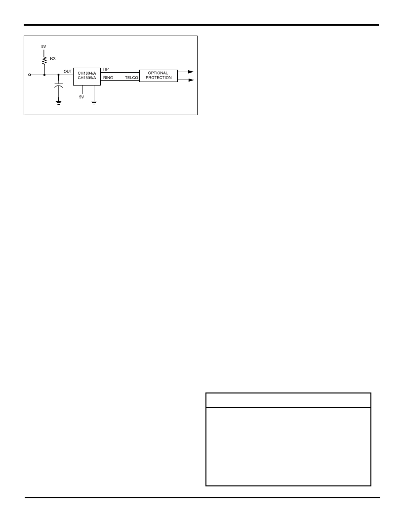
Figure 2. Application Diagram CH1804/A, or half of a CH1809/A
Dual Cut Line Detector
Table 1. CH1804/A, CH1809/A Pin Description
PIN
DESCRIPTION FOR CH1809/A
CH1804/A
1
2
3
4
5
6
7
8
9
10
Tip 1 - Telco 1
Ring 1 - Telco1
N.C.
Out1 - Active High Output 1
V
- 5 Volts + 10%
Gnd - Ground
Out2 - Active High Output 2
N.C.
Tip 2 - Telco 2
Ring 2 - Telco 2
Tip 1- Telco 1
Ring 1
N.C.
Out1
V
Gnd
N.C.
N.C.
N.C.
N.C.
相關(guān)PDF資料 |
PDF描述 |
|---|---|
| CH1808 | Telephone Circuit (Support) |
| CH1809 | CUT LINE DETECTOR|SIP|10PIN|PLASTIC |
| CH1809A | LOOP TRANSCEIVER/DETECTOR|SIP|10PIN|PLASTIC |
| CH1810 | Data Access Arrangement (DAA) |
| CH1817-ET | Data Access Arrangement (DAA) |
相關(guān)代理商/技術(shù)參數(shù) |
參數(shù)描述 |
|---|---|
| CH1808 | 制造商:未知廠家 制造商全稱:未知廠家 功能描述:Telephone Circuit (Support) |
| CH1809 | 制造商:未知廠家 制造商全稱:未知廠家 功能描述:CUT LINE DETECTOR|SIP|10PIN|PLASTIC |
| CH1809A | 制造商:未知廠家 制造商全稱:未知廠家 功能描述:LOOP TRANSCEIVER/DETECTOR|SIP|10PIN|PLASTIC |
| CH1810 | 制造商:未知廠家 制造商全稱:未知廠家 功能描述:Data Access Arrangement (DAA) |
| CH1811 | 制造商:未知廠家 制造商全稱:未知廠家 功能描述:Telecommunication IC |
發(fā)布緊急采購,3分鐘左右您將得到回復(fù)。